
Vehicular front fog lamp and daytime running lamp combination and constructing method thereof

A technology for front fog lights and running lights, which is applied in the direction of headlights, vehicle parts, lighting and heating equipment, etc., can solve the problem of less adoption of low-end models, and achieve the effects of convenient use, simple and effective solutions, and convenient switching.

Pending Publication Date: 2018-01-30
HASCO VISION TECHNOLOGY CO LTD
View PDF9 Cites 1 Cited by
  • Summary
  • Abstract
  • Description
  • Claims
  • Application Information

AI Technical Summary

Problems solved by technology

[0003] At present, the daytime driving in China is only optional, and most low-end models are rarely used due to cost reasons.

Method used


Image

  • Vehicular front fog lamp and daytime running lamp combination and constructing method thereof
  • Vehicular front fog lamp and daytime running lamp combination and constructing method thereof
  • Vehicular front fog lamp and daytime running lamp combination and constructing method thereof

Examples


Embodiment 1

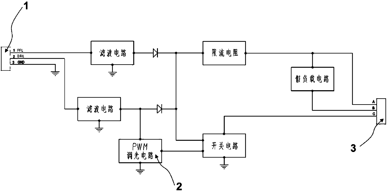
[0029] see figure 1 , for LED front fog lights, pulse width modulation (PWM) is added to adjust the duty cycle, so as to meet the LED brightness required for DRL (daytime running lights) light distribution. And a group of motor dimming system is added to ensure the adjustment of the front fog lamp and DRL light pattern.

[0030] like figure 1 As shown, the voltage signal enters the control circuit through the input terminal 1, and is processed by the filter circuit and the current limiting circuit, and the corresponding control signal is output from the output terminal 3. For the DRL circuit, the voltage signal is processed through the PWM circuit 2 alone, and the voltage demand is reduced according to the duty cycle adjustment, and the brightness of the LED is adjusted through the output terminal 3 .

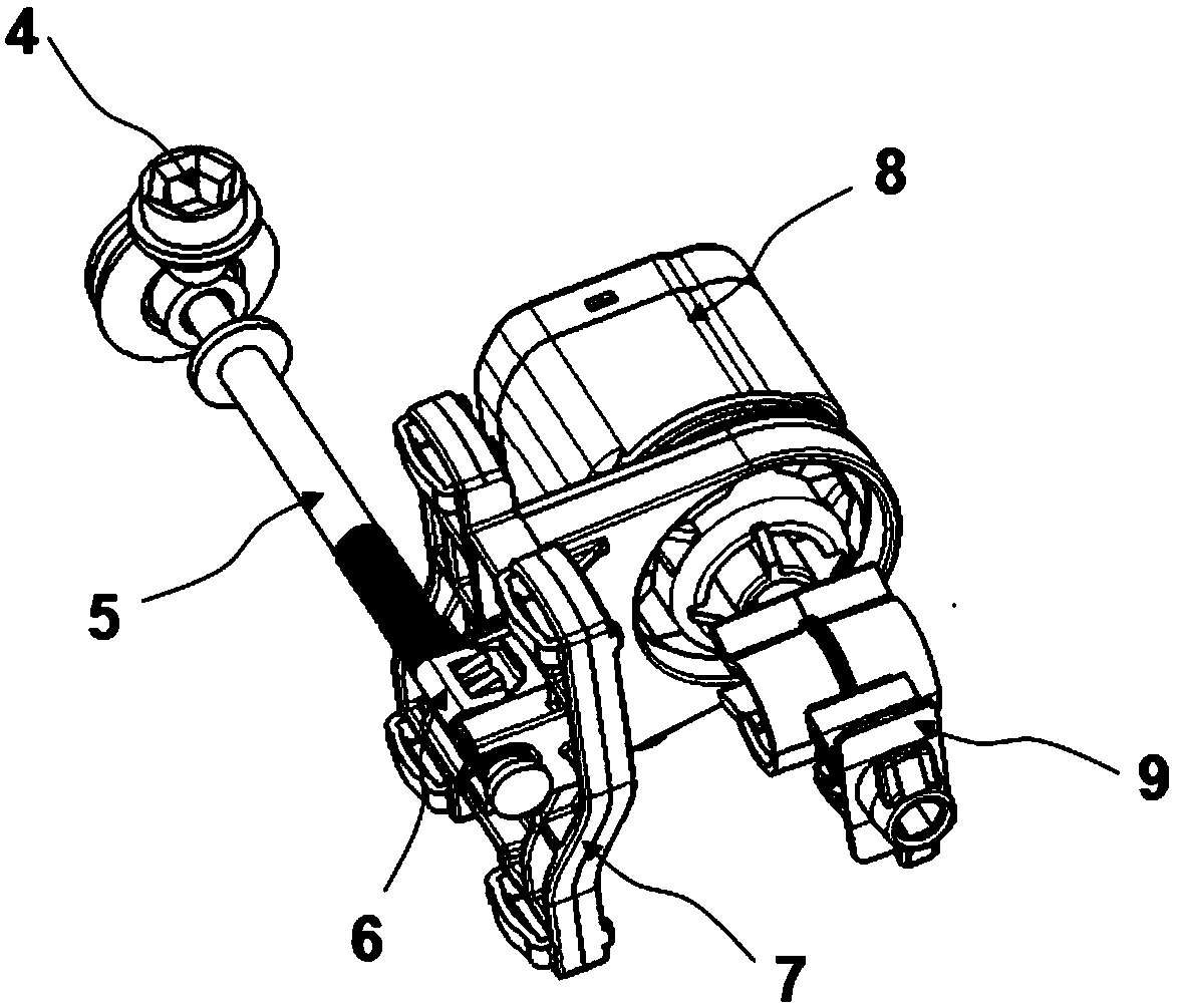
[0031] figure 2 Dimming system for motors. The hand-adjusting nut 4 can be used for the dimming requirement of the normal function of the front fog lamp. The dimming scre...

Embodiment 2

[0036] The difference between this embodiment and the first embodiment lies in the use of different optical systems, Figure 7 It is a schematic diagram of the modular implementation used in this embodiment. The motor dimming system 24 is fixed on the optical module system 23, and the switching of the light type is realized through the adjustment of the motor. The control module 25 provides different voltage signals required for the conversion of the two functions to ensure the power supply requirements of the LEDs. The light distributing mirror 21 and the lamp body 22 constitute the outer contour and space of the lamp.

[0037] The present invention can realize the multiplexing of the front fog lamp and the DRL. For daytime driving, the DRL function can be turned on; while driving at night, it can be switched to front fog lights. For bad weather conditions, it can be switched to the front fog lamp auxiliary lighting at any time. One light for two purposes, the scheme is s...


PUM


Abstract

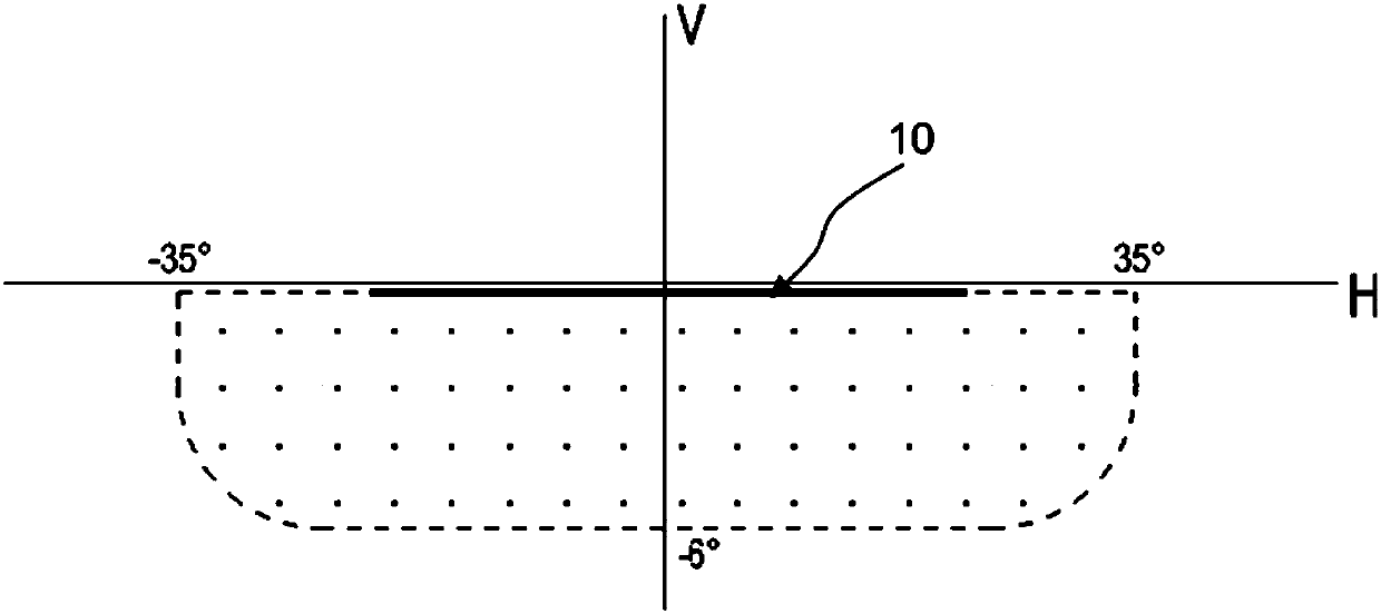
The invention relates to a vehicular front fog lamp and daytime running lamp combination, comprising a motor dimming system, a PWM (pulse width modulation) circuit control system, and an optical system; the PWM circuit control system is electrically connected with an LED light source, the LED light source may be adjusted to provide two brightness modes satisfactory to a front fog lamp and a daytime running lamp through the PWM circuit control system, the motor dimming system is connected with the optical system, and light patterns are present in above and top positions, respectively corresponding to the daytime running lap and the front fog lap having a low beam check line. The front fog lamp and DRL (daytime running lamp) are combined herein. In daytime driving, the DRL function can be enabled; the DRL may be switched to the front fog lamp for nighttime driving as required; in bad weather, the DRL can be switched to the front fog lamp to assist in lighting at any time; the vehicular front fog lamp and daytime running lamp combination has two purposes, and is simple, economical and practical.

Description

technical field [0001] The invention relates to a vehicle lamp, specifically, a vehicle front fog lamp and daytime running lamp multiplexing lamp and a construction method thereof, which belong to the technical field of vehicle lamps. Background technique [0002] At present, the front fog lamps for vehicles are used as independent auxiliary lighting fixtures, mainly used in severe weather conditions such as heavy fog. From the realization of the light source, including bulb front fog lamps and LED front fog lamps, the functions are relatively simple, and there are cut-off requirements for the light type. As a signal light function during daytime driving, daytime running lights are commonly used in more and more mid-to-high-end models. [0003] At present, the domestic daytime driving is only optional, and most low-end models are rarely used due to cost reasons. [0004] How to promote the daytime running lights, reduce the cost of the daytime running lights, and reduce th...

Claims


Application Information

Patent Timeline
IPC IPC(8): F21S41/657F21S41/675F21V14/02F21V14/04F21W102/30F21Y115/10
Inventor 姚进陈衍恒陈翔
Owner HASCO VISION TECHNOLOGY CO LTD
Learn More