
Separated dynamic contact system having heating and cooling functions

A dynamic contact and separation technology, used in lighting and heating equipment, progressive dryers, drying solid materials, etc., can solve problems such as unreasonable drying objects, and achieve the effect of saving equipment space.

Pending Publication Date: 2018-01-30
SHENZHEN DACHENG PRECISION EQUIP CO LTD
View PDF0 Cites 0 Cited by
  • Summary
  • Abstract
  • Description
  • Claims
  • Application Information

AI Technical Summary

Problems solved by technology

[0002] At present, most of the airtight drying chambers use hot air blowers to heat the drying objects for a long time and dry the moisture. From the inside, the drying effect is only to remove part of the moisture of the object itself, and the environment it is in is still high temperature. High humidity state is extremely unreasonable for drying objects with high requirements
From the outside, the drying object is affected by factors such as external air humidity and particles, which requires the required airtight cavity to be extremely sealed, thus posing a great challenge to the installation and use of external equipment

Method used

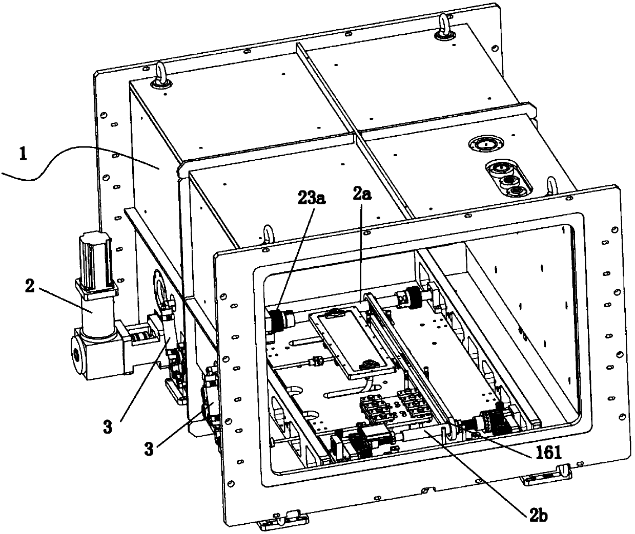
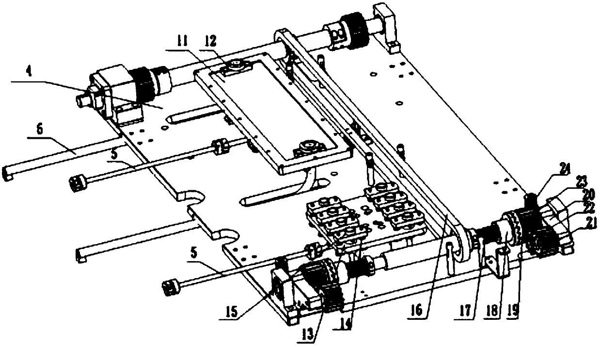
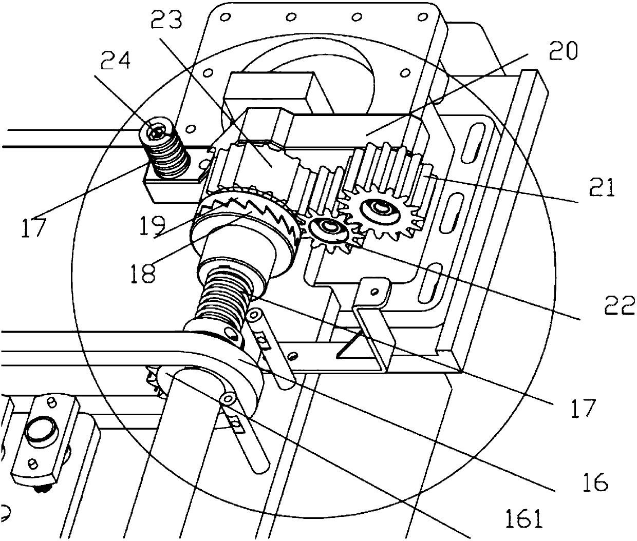

Image

  • Separated dynamic contact system having heating and cooling functions
  • Separated dynamic contact system having heating and cooling functions
  • Separated dynamic contact system having heating and cooling functions

Examples


Embodiment Construction

[0029] The specific embodiments of the present invention will be further described below in conjunction with the accompanying drawings. It should be noted here that the descriptions of these embodiments are used to help understand the present invention, but are not intended to limit the present invention. In addition, the technical features involved in the various embodiments of the present invention described below may be combined with each other as long as they do not constitute a conflict with each other.

[0030] Such as Figure 1-Figure 3 As shown, a separate dynamic contact system with heating and cooling functions, including a cavity body 1, a servo motor 2 and a cylinder 3, a cooling mechanism, a gear shifting mechanism and a heating movable contact mechanism,

[0031] The cavity main body 1 is a rectangular cavity with openings on both sides and through, and the remaining surfaces are sealed;

[0032] The cooling mechanism, the shifting gear mechanism and the heatin...


PUM


Abstract

The invention discloses a separated dynamic contact system having heating and cooling functions. The separated dynamic contact system comprises a cavity body, a servo motor, a cooling mechanism, a poking tooth mechanism and a heating movable contact mechanism, the cooling mechanism, the poking tooth mechanism and the heating movable contact mechanism are arranged on a transmission baseplate at thebottom of an inner cavity of the cavity body, an output shaft of the servo motor is connected with a main rotating shaft, driving big gears sleeve two ends of the main rotating shaft, and rotating teeth are fixedly connected in the middle section of the main rotating shaft; the separated dynamic contact system further comprises a driven rotating shaft and a chain, driven big gears sleeve two endsof the driven rotating shaft, rotating teeth, a first ratchet wheel, a second ratchet wheel and an axial compression spring are fixedly connected in the middle section of the driven rotating shaft, the first ratchet wheel and the second ratchet wheel are meshed with each other, the axial compression spring sleeves the driven rotating shaft, the second ratchet wheel is fitted to a driving big gear, and the chain sleeves the rotating teeth of the main rotating shaft and the driven rotating shaft. The system has the advantage that power transmission is smooth and free of clamping stagnation.

Description

technical field [0001] The invention relates to the technical field of drying equipment, in particular to a separate dynamic contact system with heating and cooling functions. Background technique [0002] At present, most of the airtight drying chambers use hot air blowers to heat the drying objects for a long time and dry the moisture. From the inside, the drying effect is only to remove part of the moisture of the object itself, and the environment it is in is still high temperature. High humidity state is extremely unreasonable for drying objects with high requirements. From the outside, the drying object is affected by factors such as external air humidity and particles, which requires the required airtight cavity to be well sealed, which poses a great challenge to the installation and use of external equipment. For example, the drying object is a lithium-ion battery, and water, as a trace component in the electrolyte, has a certain influence on the formation of the se...

Claims


Application Information

Patent Timeline
IPC IPC(8): F26B15/00F26B25/02
Inventor 张孝平
Owner SHENZHEN DACHENG PRECISION EQUIP CO LTD
Learn More