Method for dismounting-mounting semiconductor vacuum-pumping equipment

A kind of vacuum equipment, semiconductor technology, applied in the direction of hand tools, manufacturing tools, etc., can solve the problems of inconvenience, space waste, etc., and achieve the effect of simple structure

Inactive Publication Date: 2007-03-28
四川中安恒科技有限公司
View PDF0 Cites 2 Cited by
  • Summary
  • Abstract
  • Description
  • Claims
  • Application Information

AI Technical Summary

Problems solved by technology

[0004] Because the space for auxiliary supporting tools should be reserved under the vacuum equipment, it causes waste of space, and the disassembly and assembly process is completed in a very small space on the side of the PM, which is very inconvenient

Method used


Image

  • Method for dismounting-mounting semiconductor vacuum-pumping equipment
  • Method for dismounting-mounting semiconductor vacuum-pumping equipment

Examples


Embodiment Construction

[0031] The following examples are used to illustrate the present invention, but are not intended to limit the scope of the present invention. Those of ordinary skill in the relevant technical field can also make various changes and modifications without departing from the spirit and scope of the present invention. Therefore All equivalent technical solutions also belong to the category of the present invention, and the scope of patent protection of the present invention should be defined by each claim.

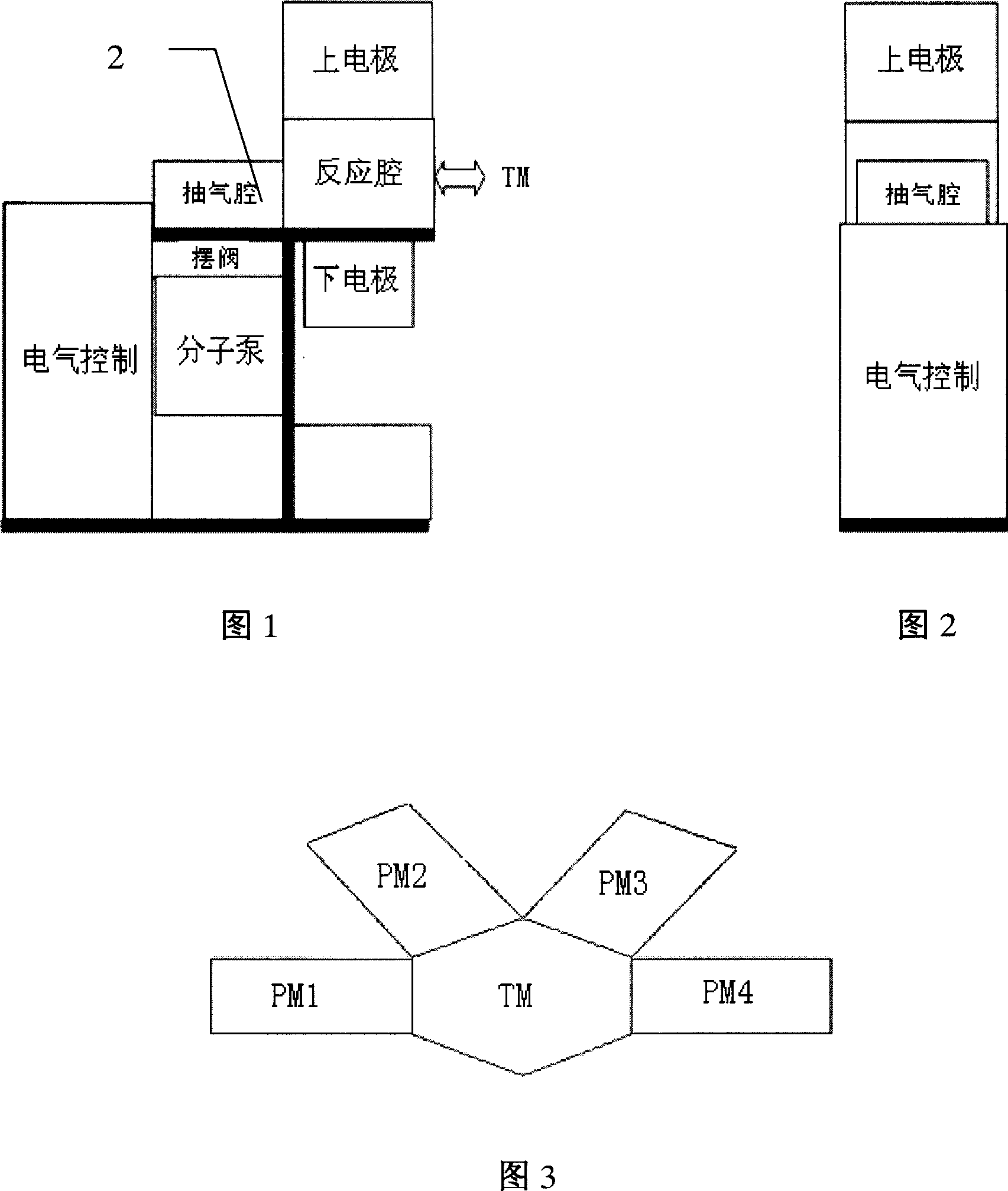
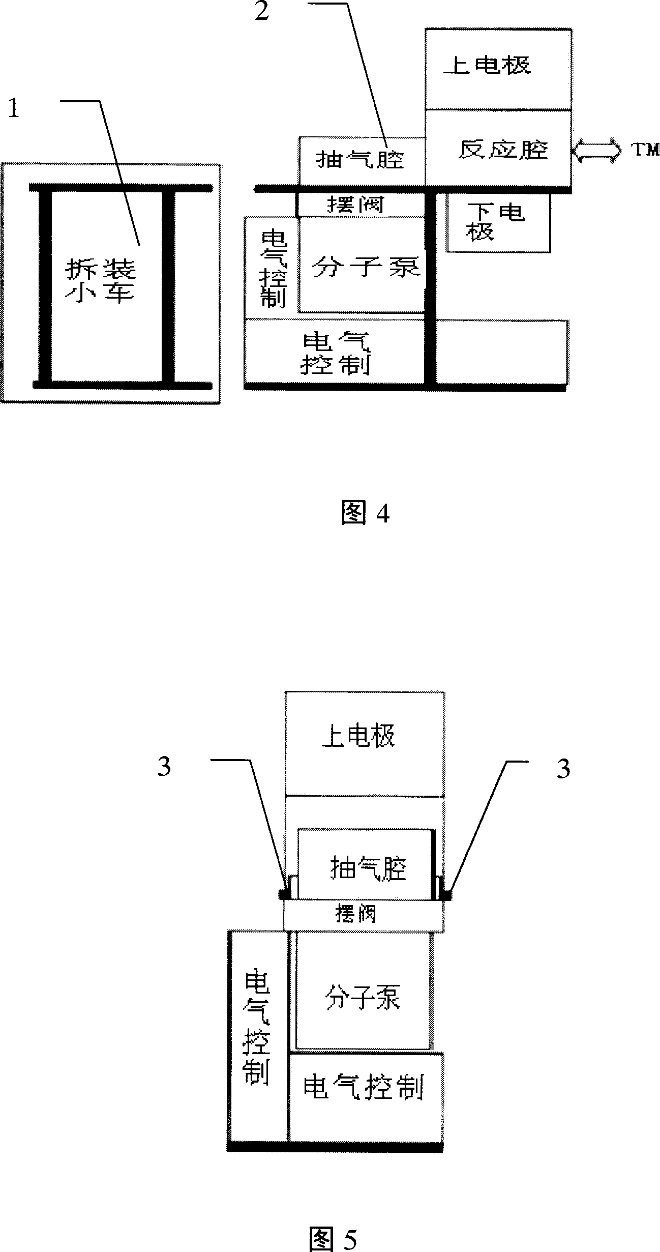
[0032] A method for disassembling and assembling semiconductor vacuum equipment, which can conveniently remove the vacuum equipment from the semiconductor processing equipment. As shown in the rear view in Figure 3, a linear slide rail 3 is respectively installed on the left and right sides of the inner side of the upper beam of the bracket 2. The guide rail of the linear slide rail 3 is fixed on the bracket, and the slider of the linear slide rail 3 is installed in the air suc...


PUM


Abstract

The present invention relates to an evacuation equipment for disassembling and assembling semiconductor. Said evacuation equipment includes the following several portions: supporting frame, upper beam, slide supporting component, evacuation cavity, swinging valve, reaction cavity, molecular pump and assembling and disassembling carriage. Besides, said invention also provides its concrete operation method for disassembling and assembling semiconductor.

Description

technical field [0001] The invention relates to a method for disassembling and assembling equipment, in particular to a method for disassembling and assembling semiconductor vacuum equipment. Background technique [0002] In the physical and chemical deposition of thin films, etching and other semiconductor processing processes, it is necessary to place silicon wafers in a clean vacuum chamber for microelectronics processes. To obtain a clean chamber, the chamber is usually evacuated to a high vacuum state using vacuum equipment (such as pendulum valves, molecular pumps, etc.) before the process gas is introduced. Some current semiconductor processing equipment (PM) adopt the structure shown in Figure 1 and Figure 2. The chamber is supported by a trolley bracket, the vacuum equipment is installed and fixed on the chamber, and the electrical control box, power supply, water and electricity are closely distributed around the chamber. Gas pipeline etc. Wafers are transferred ...

Claims


Application Information

Patent Timeline
Patent Type & Authority Applications(China)
IPC IPC(8): B25B27/14
Inventor 胡谦
Owner 四川中安恒科技有限公司
Why Eureka
Try Eureka