Welding method for large-curvature thick plate box type rotary steel ladder box body

A thick plate box type and welding method technology, which is applied in the direction of welding equipment, welding equipment, auxiliary welding equipment, etc., can solve the problem of large amount of welds inside the box, difficult to control shape and size, and difficulty in the influence of special-shaped components affected by welding heat shrinkage. Control and other issues, to achieve the effect of low manufacturing cost investment, simple welding method, and reduce the difficulty of welding seam

Active Publication Date: 2018-02-02
CHINA FIRST METALLURGICAL GROUP
View PDF6 Cites 4 Cited by
  • Summary
  • Abstract
  • Description
  • Claims
  • Application Information

AI Technical Summary

Problems solved by technology

The rotary ladder targeted by this patent has a three-dimensional space structure of spiral blades. The section of the rotary steel ladder is a unequal trapezoid, and the overall box structure is not only difficult to control its shape and size during production, but also has a large amount of welds inside the box. It is difficult to weld the position of the internal partition and the bottom plate weld, the internal partition and the panel weld cannot be welded, the spatial position of the side plate and the bottom panel is complicated, and it is difficult to control the influence of welding heat shrinkage on the special-shaped components. Therefore, It is necessary to formulate a reasonable welding method to ensure the manufacturing accuracy and quality of the rotary steel ladder

Method used


Image

  • Welding method for large-curvature thick plate box type rotary steel ladder box body
  • Welding method for large-curvature thick plate box type rotary steel ladder box body
  • Welding method for large-curvature thick plate box type rotary steel ladder box body

Examples


Embodiment Construction

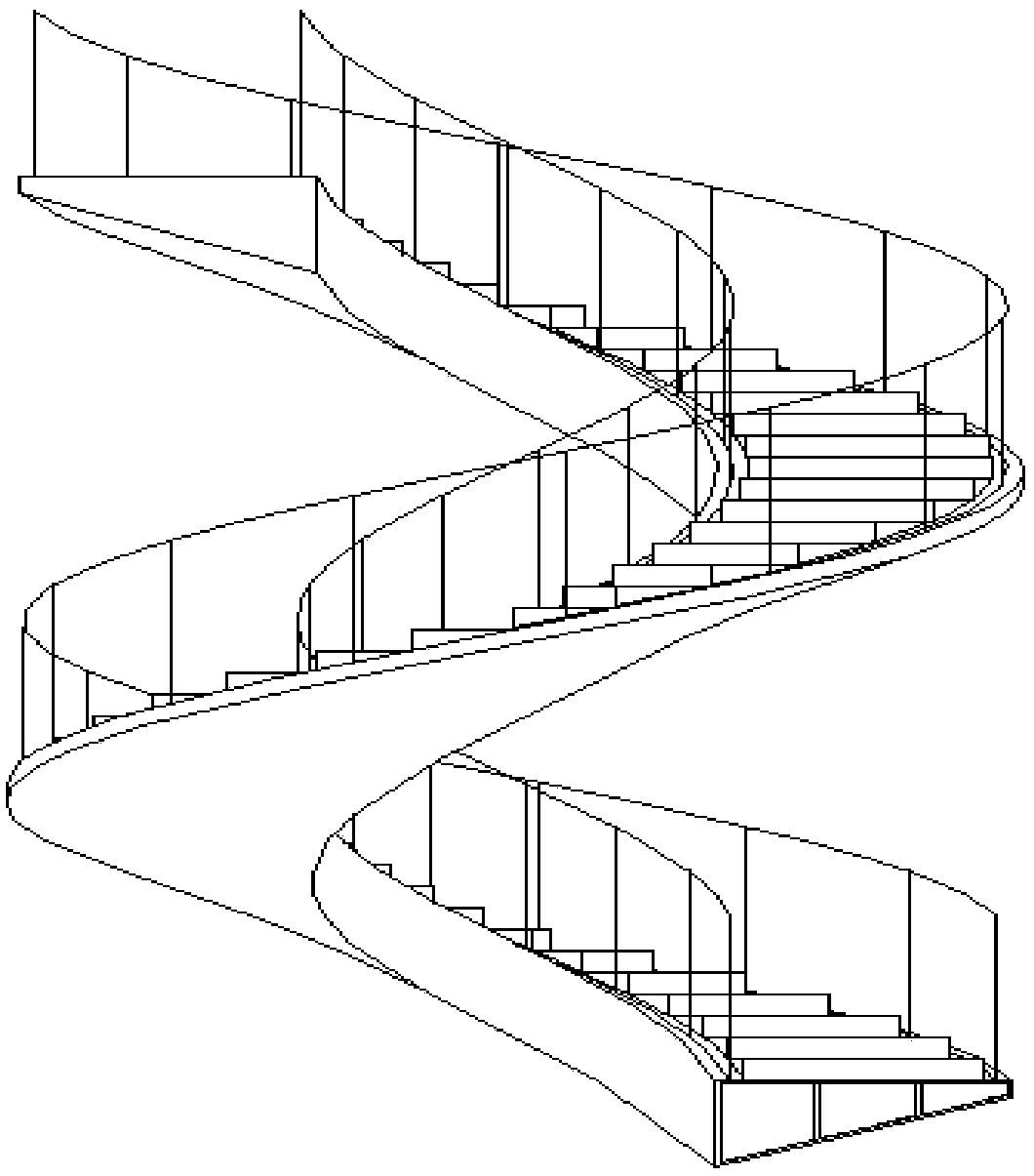
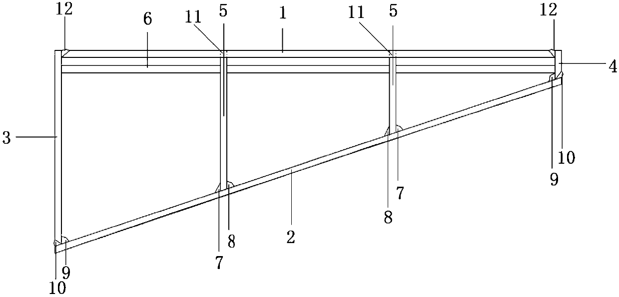
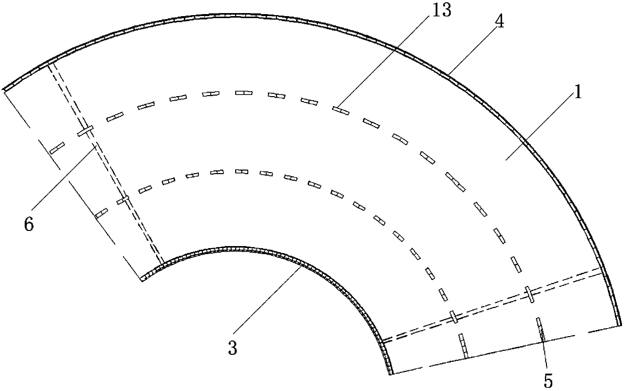
[0024] The technical scheme of the present invention will be further specifically described through the examples below in conjunction with the accompanying drawings. A welding method for a large-curvature thick plate box-type rotary steel ladder box is characterized in that: figure 1 As shown, the rotating steel ladder box includes a cover plate 1, a bottom plate 2, an inner side plate 3 and an outer side plate 4 that are pressed and formed according to the size of the design drawing. Anti-deformation support 6 is provided between the boards and between the partition boards.

[0025] The welding method comprises the steps of:

[0026] Step 1. Place the bottom plate 2 on the tire frame, position the partition plate 5, and perform edge milling on the contact end of the partition plate 5 and the bottom plate 2 according to the slope of the bottom plate 2, so as to ensure that the bottom of the partition plate 5 is close to the bottom plate 2, and the tire frame It is the tire fr...


PUM

PropertyMeasurementUnit
thicknessaaaaaaaaaa

Abstract

The invention provides a welding method for a large-curvature thick plate box type rotary steel ladder box body. The welding method is characterized in that the rotary steel ladder box body comprisesa cover plate, a bottom plate, an inner side plate and an outer side plate which are formed in a pressed mode according to the sizes of a design drawing; a plurality of separating plates are arrangedbetween the inner side plate and the outer side plate; and anti-deformation supports are arranged between the separating plates and the inner and outer side plates as well as between the separating plates. According to the welding method, through the measures of setting of grooves of assembled steel plates, supporting and reinforcement before welding, reasonable arrangement of the welding joint welding sequence, adoption of symmetrical welding and the like, the problems of large deformation, difficult control and the like prone to occurring during welding of thick plates are reduced, deformation correction in the later period is reduced, and therefore the purpose of lowing manufacturing cost is realized. By means of the welding method, the welding difficulty can be lowered, turning over isnot needed during component welding, a welding joint can be formed at a time, the thermal contraction deformation is small, and the accuracy and quality of manufacturing of a rotary steel ladder areimproved.

Description

technical field [0001] The invention belongs to the technical field of welding technology, and in particular relates to a welding method for a large-curvature thick plate box-type rotary steel ladder box. Background technique [0002] With the widespread application of steel structures in China, architectural modeling puts forward higher requirements for the manufacture of steel structures, especially in large public service places, where steel structure spiral stairs are often encountered. Compared with cast-in-place concrete, the steel structure spiral ladder has the characteristics of light structure, beautiful appearance and environmental protection. The rotary ladder targeted by this patent has a three-dimensional space structure of spiral blades. The section of the rotary steel ladder is a unequal trapezoid, and the overall box structure is not only difficult to control its shape and size during production, but also has a large amount of welds inside the box. It is di...

Claims


Application Information

Patent Timeline
Patent Type & Authority Applications(China)
IPC IPC(8): B23K37/00B23K31/02
CPCB23K31/02B23K37/00
Inventor 章鹏南足刚龙昭毅梁盈
Owner CHINA FIRST METALLURGICAL GROUP
Why Eureka
Try Eureka