Method and clamping device for numerical control machining of component closed corner

A clamping device and part technology, applied in the field of CNC machining parts closed angle, method and clamping device, can solve the problems of insufficient five-axis swing angle machining stroke, insufficient Y-direction stroke, etc., to expand the machinable range and reduce Y The effect of the stroke

Pending Publication Date: 2018-02-02
XIAN AIRCRAFT IND GROUP
View PDF10 Cites 4 Cited by
  • Summary
  • Abstract
  • Description
  • Claims
  • Application Information

AI Technical Summary

Problems solved by technology

[0007] Through this processing method and clamping device, the problem of insufficient Y-direction travel in the vertical processing mode of the rotary table-type vertical-horizontal conversion five-axis machining center and the insufficient travel of the five-axis swing angle processing in the horizontal processing mode are solved, greatly expanding The processing range of the equipment

Method used


Image

  • Method and clamping device for numerical control machining of component closed corner
  • Method and clamping device for numerical control machining of component closed corner
  • Method and clamping device for numerical control machining of component closed corner

Examples


Embodiment Construction

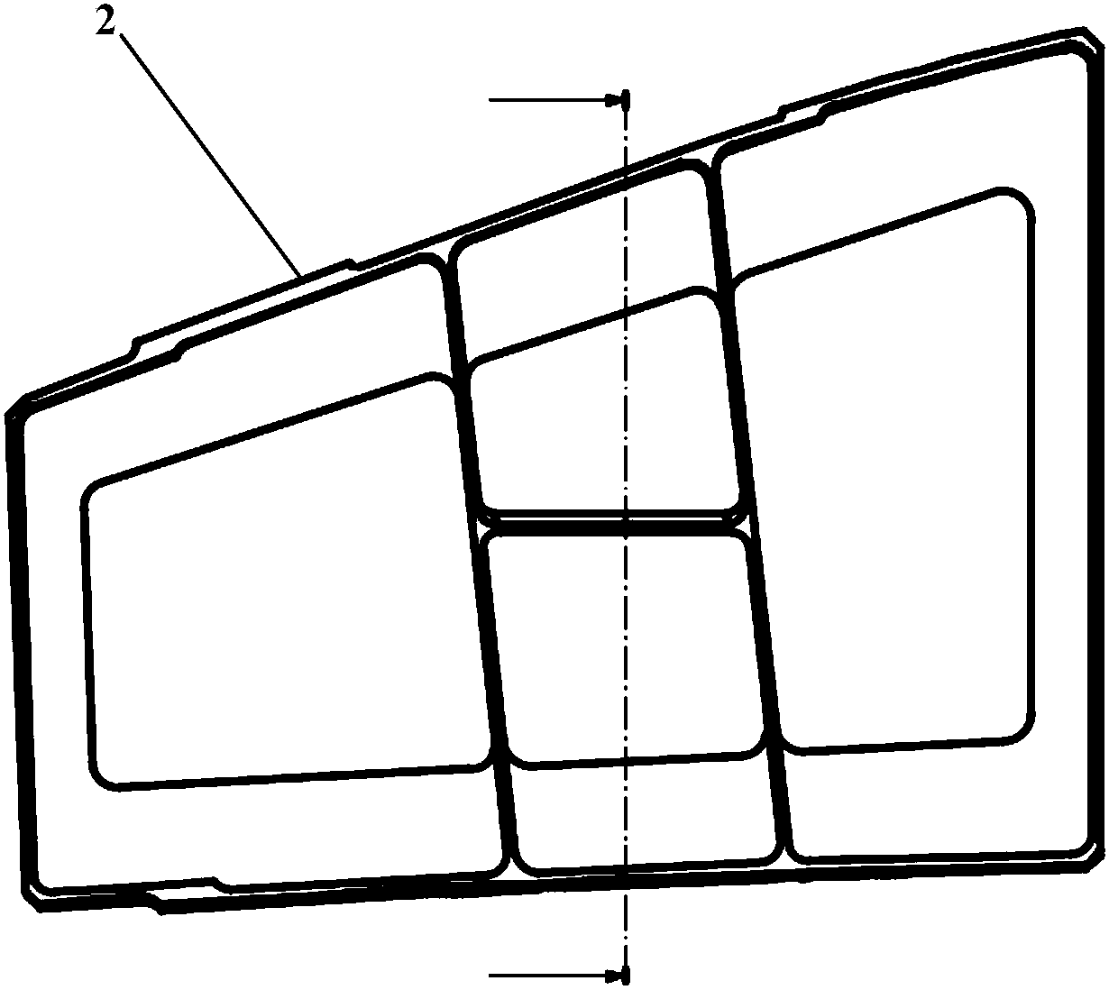
[0024] This embodiment takes a part 2 with a double-sided cavity structure as an example to describe in detail. For a schematic diagram of the part structure, see image 3 , the section structure see Figure 4 . The part is a double-sided multi-groove structure, with edge plates and vertical ribs with varying angles, and the maximum closed angle angle β.

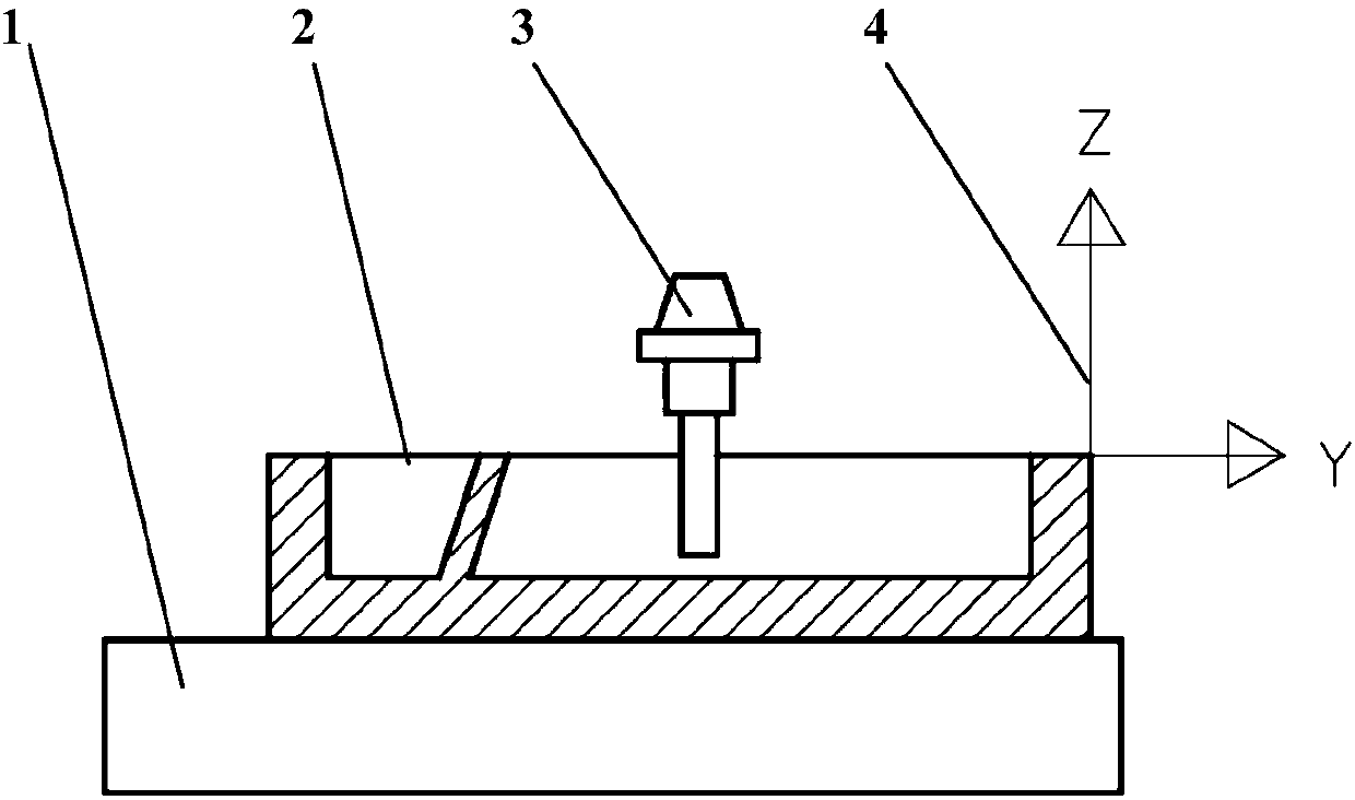
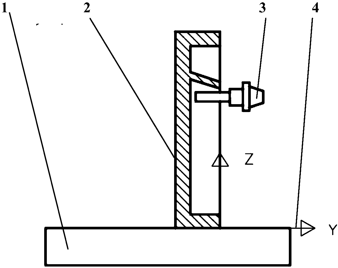
[0025] First, the clamping device 5 for closed-angle CNC machining is designed according to the part structure. Figure 5 It is the axonometric drawing of the closed-angle CNC machining clamping device, Image 6 It is a side view of the closed-angle CNC machining clamping device. The cross section of the clamping device 5 is a right-angled trapezoid, narrow at the top and wide at the bottom. The bottom plane 13 is rectangular and fits the machine tool platform; the top plane 7 is also rectangular and used for Z-direction tool setting during processing; the top plane 7 is parallel to the bottom plane 13 . A step 12 protr...


PUM


Abstract

The invention discloses a method and a clamping device for numerical control machining of a component closed corner. The cross section of the clamping device is in a right trapezoid shape. The clamping device comprises a top plane and a bottom plane which are parallel to each other, and further comprises an oblique plane. The angle formed between the oblique plane and the vertical direction is larger than the maximum closed corner angle on a component. Two positioning holes and a plurality of bolt holes are distributed in the oblique plane. The top plane is provided with a vertical datum hole,and a reference edge perpendicular to the bottom plane is arranged below the oblique plane. The clamping device is arranged on a platform of a numerical control machine tool, the bottom plane is attached to the machine tool platform, the reference edge is parallel to the X direction of the machine tool, and the component is positioned and installed on the oblique plane of the clamping device. A machining coordinate system is established by utilizing the relative relation of the datum hole and the positioning holes in the clamping device, and the original point of the machining coordinate system coincides with the center of the datum hole. Five-axis oscillating angle machining of a workpiece is finished through the numerical control machining program established under the machining coordinate system.

Description

technical field [0001] The invention relates to the technical field of numerical control machining, in particular to a method and a clamping device for a closed angle of a numerical control machining part. Background technique [0002] In CNC milling, the processing methods are generally divided into vertical processing and horizontal processing according to the installation method of parts and the main processing direction of the machine tool spindle. In the vertical processing mode, the parts are installed horizontally, and the main processing direction of the machine tool spindle is the vertical direction, such as figure 1 As shown; in the horizontal processing mode, the parts are installed vertically, and the main processing direction of the machine tool spindle is horizontal, such as figure 2 shown. [0003] However, in the currently widely used rotary table-type vertical-horizontal conversion five-axis machining center equipment, there are certain limitations regard...

Claims


Application Information

Patent Timeline
Patent Type & Authority Applications(China)
IPC IPC(8): B23Q3/06B23Q1/25
CPCB23Q1/25B23Q3/06
Inventor 田辉尹佳马引劳
Owner XIAN AIRCRAFT IND GROUP
Why Eureka
Try Eureka