Portable umbrella rapid spin-drying equipment

A portable umbrella technology, which is applied in the field of portable umbrella drying equipment, can solve the problems of unsafe and easy to produce peculiar smell, and achieve the effects of convenient operation, no energy consumption, and prevention of survival and reproduction

Inactive Publication Date: 2018-02-02
浦江县顺光科技有限公司
View PDF4 Cites 9 Cited by
  • Summary
  • Abstract
  • Description
  • Claims
  • Application Information

AI Technical Summary

Problems solved by technology

The beneficial effects of the invention are: (1) Simple structure, (2) The umbrella can be quickly dried, but the inve

Method used


Image

  • Portable umbrella rapid spin-drying equipment
  • Portable umbrella rapid spin-drying equipment

Examples


Embodiment 1

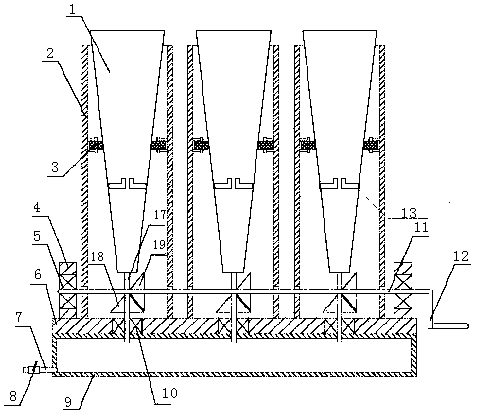
[0019] Such as Figure 1-2 As shown, the portable umbrella quick-drying equipment includes a water reservoir 9, a base 6, and an umbrella holding barrel 1, and is characterized in that several tapered umbrella holding barrels 1 are evenly distributed above the base 6, so that The end of the umbrella holding barrel 1 is connected to one end of the coaxial hollow shaft 17, the other end of the hollow shaft 17 is covered with a second bearing 10 and connected to the reservoir 9 through the base 6, the middle of the hollow shaft 17 A first bevel gear 18 is fixed, and a horizontal drive shaft 11 is arranged in the middle of the hollow rotating shaft 17. A second bevel gear 19 is fixed on the drive shaft 11, and the second bevel gear 19 is connected with the first bevel gear. 18 are meshed with each other to form a meshing transmission. The front and rear ends of the drive shaft 11 are provided with brackets 4, and the inside of the bracket 4 is provided with a first bearing 5. The ...

Embodiment 2

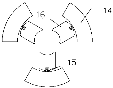
[0023] Portable umbrella quick-drying equipment, when you need to dry the umbrella, first put the umbrella into the umbrella holding barrel 1, the clamping device in the umbrella holding barrel 1 will clamp it according to the size of the umbrella, and then shake it The handle 12, driven by the crank handle 12, the drive shaft 11 and the second bevel gear 19 rotate rapidly, and the second bevel gear 19 will drive the first bevel gear 18, the hollow rotating shaft 17 and the umbrella holder 1 to rotate rapidly while rotating rapidly. When rotating, the umbrella holding tube 1 rotates rapidly, and under the action of centrifugal force, the rainwater remaining on the umbrella will be thrown out. Since the umbrella holding tube 1 is tapered, the thrown rainwater will quickly move along the direction of the umbrella. The inner wall of the holding tube 1 flows into the hollow rotating shaft 17, and finally flows into the water reservoir 9 through the hollow rotating shaft 17, so as t...


PUM


Abstract

The invention discloses portable umbrella rapid spin-drying equipment, and belongs to the technical field of umbrella spin-drying equipment. The umbrella rapid spin-drying equipment comprises a waterstorage pool, a base, an umbrella containing barrel and a driving shaft which is horizontally arranged. A plurality of tapered umbrella containing cylinders are evenly distributed above the base, oneend of a hollow rotary shaft is connected to the position below the middle of the tail end of the umbrella containing barrel, and the other end of the hollow rotary shaft is sleeved with a second bearing and connected with the water storage pool through the base. A first bevel gear is fixed to the middle of the hollow rotary shaft, supports are arranged at the front end and the rear end of the driving shaft correspondingly, a first bearing is arranged in each of the supports, and the first bearings are connected with the driving shaft. A second bevel gear is fixed to the driving shaft, the second bevel gear is engaged with the first bevel gear to form engaged transmission, and a crank is fixed to the tail end of the driving shaft. By adopting the portable umbrella rapid spin-drying equipment, water on umbrellas can be rapidly spin-dried, a clamping device is mounted so that the umbrellas of any types can be placed into the umbrella containing barrel, and meanwhile, it is ensured that the umbrellas are not thrown out from the umbrella containing barrel in the spin-drying process.

Description

technical field [0001] The invention belongs to the technical field of umbrella drying equipment, and in particular relates to a portable umbrella quick drying equipment. Background technique [0002] When returning from a trip on a rainy day, the used umbrella is wet. People are used to throwing the umbrella in the corridor and running to the bathroom in a hurry, fearing that the rain will stain the floor, but it often backfires. In addition, the rainwater thrown out not only stained the ground and walls of the corridor, but also may throw the pedestrians around if you are not careful. There have been some umbrella drying equipment on the market, but most of them are not suitable for home use because they are bulky, occupy a large area, consume high energy, or are cumbersome to use and have low efficiency and effectiveness. [0003] Prior art such as Chinese Invention Authorization Document, Authorization Notice No. CN 204787673U This invention discloses a quick umbrella d...

Claims


Application Information

Patent Timeline
IPC IPC(8): F26B11/08F26B5/08F26B25/00C09D5/14C09D5/16C09D171/00
CPCF26B11/08C08K2003/2248C08L2205/025C08L2205/03C09D5/14C09D5/1675C09D5/1687C09D171/00F26B5/08F26B25/00F26B2210/10C08L83/04C08K3/22C08K5/0058
Inventor 胡光琼
Owner 浦江县顺光科技有限公司
Why Eureka
Try Eureka