Efficient drying device for textile processing

A drying device, high-efficiency technology, applied in the field of textile processing, can solve the problem of not being able to dry at the same time, achieve the effect of expanding the drying area and preventing damage

Inactive Publication Date: 2018-02-02
薛帅龙
0 Cites 15 Cited by

AI-Extracted Technical Summary

Problems solved by technology

[0004] Aiming at the deficiencies of the prior art, the present invention provides a high-efficiency drying device for textile processing, which...

Method used

When in use, the S-shaped heating pipe 5 is blown downwards by the fan 4, so that the heat of the S-shaped heating pipe 5 is dried downwards to the textiles 7, and the drying of the textiles 7 is enlarged by the setting of the combination roller 6 Dry area, by starting the first motor 8 to drive the rotation of the reciprocating screw rod 10...

Abstract

The invention discloses a high-efficiency drying device for textile processing, which comprises a base, a first belt and a second belt, the top of the base is fixedly connected with a connecting block, the top of the connecting block is fixedly connected with an organic case, and the Fans are fixedly connected to both sides of the top of the inner chamber of the case, and the fan runs through the case and extends to the outside of the case. An S-shaped heating pipe is installed on the top of the inner chamber of the case and directly below the fan. The front surface of the case Combination rollers are arranged, and the surface of the combination rollers is driven and connected with textiles. This high-efficiency drying device for textile processing, through the arrangement of S-shaped heating tubes, textiles, reciprocating screw rods, and heating sheets, jointly constructs a high-efficiency drying device for textile processing that can dry both sides at the same time. The device expands the drying area of ​​the textiles, and the combination of the above structures solves the problem that the two sides of the high-efficiency textile processing drying device cannot be dried at the same time.

Application Domain

Technology Topic

Leather beltTextile processing +3

Image

  • Efficient drying device for textile processing
  • Efficient drying device for textile processing

Examples

  • Experimental program(1)

Example Embodiment

[0018] The following will clearly and completely describe the technical solutions in the embodiments of the present invention with reference to the accompanying drawings in the embodiments of the present invention. Obviously, the described embodiments are only some, not all, embodiments of the present invention. Based on the embodiments of the present invention, all other embodiments obtained by persons of ordinary skill in the art without making creative efforts belong to the protection scope of the present invention.
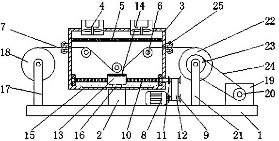
[0019] see Figure 1-2 , a high-efficiency drying device for textile processing, including a base 1, a first belt 12 and a second belt 24, the top of the base 1 is fixedly connected with a connecting block 2, and the left side of the base 1 is fixedly connected with a first support column 17 , the top of the first support column 17 is movably connected with a discharge roller 18 through a rotating shaft, the surface of the discharge roller 18 is in transmission connection with the textile 7 that runs through the left side of the cabinet 3, the top of the connecting block 2 is fixedly connected with the cabinet 3, and inside the cabinet 3 The bottom of the cavity is provided with a chute 15, and the inner cavity of the chute 15 is slidably connected with a slider 16, and the end of the slider 16 away from the chute 15 is fixedly connected with the threaded block 13, and by setting the chute 15 and the slider 16, the During the drying process of the heating sheet 14, the heating sheet 14 is always facing the dried textile 7 with the front side. The top of the cabinet 3 and the right side of the first motor 8 are fixedly connected with a second motor 19. The second motor 19 The output shaft of the output shaft is fixedly connected with the third belt pulley 20, the second support column 21 is fixedly connected between the first motor 8 and the second motor 19, and the top of the second support column 21 is respectively movably connected with the receiving roller 22 and the The fourth belt pulley 23, the surface of the receiving roller 22 is connected with the textile 7 running through the right side of the cabinet 3, the third belt pulley 20 and the fourth belt pulley 23 are connected by the second belt 24, and the second motor 19, put The setting of feeding roller 18 and receiving roller 22 can automatically collect the textiles 7 after the textiles 7 are dried. Both sides of the top of the inner chamber of the cabinet 3 are fixedly connected with fans 4, and the fans 4 run through the cabinets 3 and extend to On the outside of the case 3, an S-shaped heating tube 5 is installed on the top of the inner cavity of the case 3 and directly below the fan 4. The front surface of the case 3 is provided with a combination roller 6, and the surface of the combination roller 6 is connected with a textile 7 through transmission. The upper and lower sides of the cabinet 3 and extending to the outside of the cabinet 3 are equipped with symmetrical guide roller shafts 25 through brackets. The surface of the guide roller shaft 25 is provided with anti-scratch sponges. Through the setting of the guide roller shaft 25, the textiles 7 can enter and exit the cabinet 3 When drying, it provides support, and at the same time, the anti-scratch sponge on the surface can prevent damage to the textile 7 during the rolling process. And the right side of the connecting block 2 is fixedly connected with the first motor 8, the output shaft of the first motor 8 is fixedly connected with the first belt pulley 9, and the bottom of both sides of the inner cavity of the cabinet 3 is movably connected with the reciprocating screw rod 10 through bearings. The right end of the reciprocating screw mandrel 10 runs through the right side of the cabinet 3 and extends to the outside of the cabinet 3 and is fixedly connected with a second belt pulley 11. The first belt pulley 9 and the second belt pulley are connected by the transmission of the first belt 12, and the reciprocating screw mandrel 10 The surface at one end of the inner cavity of the chassis 3 is provided with a threaded block 13 matched with the reciprocating screw rod 10, the bottom of the threaded block 13 is slidingly connected with the bottom of the inner cavity of the chassis 3, and the top of the threaded block 13 is provided with a heating plate 14, Through the setting of the S-shaped heating tube 5, the textile 7, the reciprocating screw rod 10, and the heating plate 14, a high-efficiency drying device for textile processing that can be dried on both sides at the same time is jointly constructed. The drying area of ​​7, and the combination of the above structures solve the problem that the two sides of the high-efficiency textile processing drying device cannot be dried at the same time.
[0020] When in use, the S-shaped heating pipe 5 is blown downward by the fan 4, so that the heat of the S-shaped heating pipe 5 is dried downward to the textile 7, and the drying area of ​​the textile 7 is enlarged by setting the combined roller 6, By starting the first motor 8 to drive the reciprocating screw rod 10 to rotate, thereby driving the heating plate 14 on the threaded block 13 to reciprocate within the range of the chute 15, the cooperation of the above structures achieves the effect of drying both sides at the same time , which solves the problem that the two sides of the high-efficiency textile processing drying device cannot be dried at the same time.
[0021] To sum up, the high-efficiency drying device for textile processing, through the S-shaped heating tube 5, the combined roller 6, the textile 7, the first motor 8, the first belt pulley 9, the reciprocating screw rod 10, and the second belt pulley 11 , the cooperation of the first belt 12, the threaded block 13, the heating sheet 14 and the chute 15 solves the problem that the two sides of the drying device for efficient textile processing cannot be dried simultaneously.
[0022] Although the embodiments of the present invention have been shown and described, those skilled in the art can understand that various changes, modifications and substitutions can be made to these embodiments without departing from the principle and spirit of the present invention. and modifications, the scope of the invention is defined by the appended claims and their equivalents.

PUM

no PUM

Description & Claims & Application Information

We can also present the details of the Description, Claims and Application information to help users get a comprehensive understanding of the technical details of the patent, such as background art, summary of invention, brief description of drawings, description of embodiments, and other original content. On the other hand, users can also determine the specific scope of protection of the technology through the list of claims; as well as understand the changes in the life cycle of the technology with the presentation of the patent timeline. Login to view more.

Similar technology patents

Probiotic drying equipment

Owner:绍兴迈亚塔菌检智能科技有限公司

Classification and recommendation of technical efficacy words

  • Increase the drying area
  • Avoid damage

Cloth drying device for textile processing

ActiveCN109282614AIncrease the drying areaSuitable for dryingMechanical cleaningPressure cleaningFixed frameEngineering
Owner:安徽豹子头服饰股份有限公司

Drying device for manufacturing flour

InactiveCN105248628AIncrease the drying areaSpeed up the drying processSeed preservation by dryingGrain millingEngineeringSpiral blade
Owner:CHONGQING YUXI FLOUR PROD

Grain dryer based on improvement of drying efficiency

InactiveCN108800900AReduce sheddingIncrease the drying areaSievingScreeningHot blastScrap
Owner:合肥亚卡普机械科技有限公司

Drying rack

Owner:NANJING VOCATIONAL UNIV OF IND TECH

Telescopic clothes hanger

InactiveCN105476417AIncrease the drying areaSpeed up dryingApparel holdersClothes hangerEngineering
Owner:周欣玥
Why Eureka
Try Eureka