
Vertical gravity conveying enforced cross-flow drying method and device

A drying method and drying equipment technology, applied in the direction of drying solid materials, lighting and heating equipment, heating to dry solid materials, etc., can solve the problems of not meeting the demand for high coal production, deterioration or combustion of low-flammability materials, and short drying time , to achieve the effect of increasing the through-flow drying area, less exhaust dust, and less disturbance

Inactive Publication Date: 2010-08-04
王文民
View PDF5 Cites 5 Cited by
  • Summary
  • Abstract
  • Description
  • Claims
  • Application Information

AI Technical Summary

Problems solved by technology

[0002] At present, the domestic existing drying equipment used in mining, building materials, metallurgy, ceramics, chemical industry and other industries mainly includes the following types: drum dryer, fluidized bed dryer, vibrating fluidized bed dryer, vibrating mixed flow dryer, Carrier dryers, etc. These devices have different defects, some of which have short drying time and low output, which cannot meet the high output requirements such as coal; some use high temperature drying to easily deteriorate or burn low-flammability materials such as lignite, and Prone to explosion; some have complex structures; some are easy to damage due to the use of vibration mechanisms, etc.
The existing domestic granular material drying equipment used in grain, feed and other industries mainly uses box dryers, belt dryers, fluidized bed dryers, etc., and there are also different defects, such as low thermal efficiency and low output.

Method used


Image

  • Vertical gravity conveying enforced cross-flow drying method and device
  • Vertical gravity conveying enforced cross-flow drying method and device
  • Vertical gravity conveying enforced cross-flow drying method and device

Examples


Embodiment 1

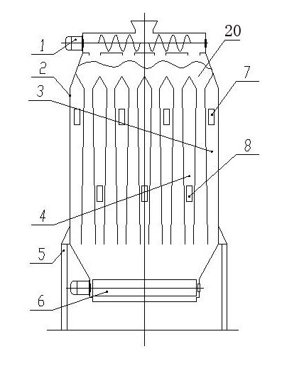
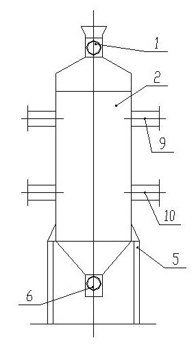
[0058] Refer to attached figure 1 , 2 , Vertical gravity conveying drum forced through-flow drying equipment includes left and right spiral distributor 1, drying bin body 2, negative pressure chamber 3, positive pressure chamber 4, frame 5, impeller unloader 6, air outlet 7, air inlet 8. Exhaust air main pipe 9, air inlet main pipe 10, wherein the dry warehouse body 2 is a steel square warehouse structure with a rectangular cross section and a heat insulation layer around it, and its upper and lower parts are respectively closed inward; the positive pressure chamber 4 and the negative pressure chamber Multiple groups of pressure chambers 3 are vertically arranged in the straight section of the drying chamber body 2, and are equal in width to the drying chamber body 2. There is a certain interval between the two chambers, and the vertical section of the interval space is an isosceles trapezoid with a small top and a large bottom; The air inlet main pipe 10 and the exhaust air ...

Embodiment 2

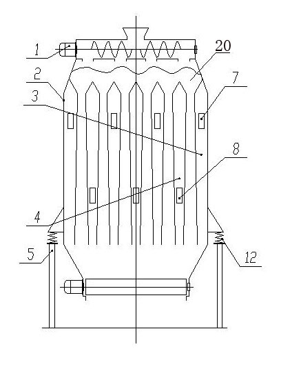
[0060] Refer to attached image 3 , 4 In this embodiment, the drying bin 2 is vibrated by the vibrating device 11, which is used to improve the vertical sinking of the material, activate the material, and increase the ability of the air flow to penetrate the material.

[0061] The difference from Embodiment 1 is that the shock-absorbing base 12 is installed on the frame 5, the drying bin body 2 is installed on the shock-absorbing base 12, and the drying bin body 2 is attached with a vibrating device 11, which can be such as electromagnetic Vibrators, mechanical vibrators, warehouse wall vibrators, vibration motors, etc. The shock absorber can be installed on the shock absorbing base by seat type or hanging type.

Embodiment 3

[0063] Refer to attached Figure 8 , in the third embodiment, three unloaders can be set according to the width of the bin body to reduce the closing angle of the lower part of the bin body and ensure that the sinking speed of the materials in the same cross-section in the drying bin body is consistent.


PUM


Abstract

The invention relates to a vertical gravity conveying enforced cross-flow drying method and a device. The invention is suitable for removing surface moisture from particle materials by utilizing hot air in the industries of mine, building materials, metallurgy, ceramics, chemical engineering and the like, and is also suitable for removing moisture from particle materials by utilizing hot air in the industries of foodstuff and feedstuff. The invention has the following technical scheme: hot airflow suitable for the dried material temperature is enforced into a storehouse; under the positive action of the external pressure, the hot airflow penetrates through the voids among the granules and is discharged out of the storehouse; the hot airflow and the material contact each other and exchange heat when the hot airflow penetrates through the voids among the granules; thus, the material temperature is increased, the moisture is evaporated, and the generated water vapor is discharged out of the storehouse along with the airflow; and under the action of gravity, the material on the same cross section in the drying storehouse continuously descends, and is continuously penetrated through and dried by the hot air in the descending process. Due to the adoption of the vertical gravity descending conveying, the invention is simple and reliable in structure; due to the adoption of the drum suction mode with multiple sets of positive pressure chambers and negative pressure chambers which are vertically arranged, the invention strengthens the airflow penetration capability, so that the airflow completely penetrates through the material, thereby enhancing the thermal efficiency; the flaky pastry mode increases the flow penetration drying area and enhances the yield; and since the material is dried in the descending process, the invention has the advantages of small disturbance, little exhaust dust and low pollution.

Description

technical field [0001] The invention relates to a vertical gravity conveying forced through-flow drying method and equipment, which is suitable for removing the external moisture of granular materials by using hot air in industries such as mines, building materials, metallurgy, ceramics, and chemical industry, and is also suitable for removing particulate matter by using hot air in the grain and feed industries. Material moisture. Background technique [0002] At present, the domestic existing drying equipment used in mining, building materials, metallurgy, ceramics, chemical industry and other industries mainly includes the following types: drum dryer, fluidized bed dryer, vibrating fluidized bed dryer, vibrating mixed flow dryer, Carrier dryers, etc. These devices have different defects, some of which have short drying time and low output, which cannot meet the high output requirements such as coal; some use high temperature drying to easily deteriorate or burn low-flam...

Claims


Application Information

Patent Timeline
Patent Type & Authority Applications(China)
IPC IPC(8): F26B3/16F26B5/04F26B17/14F26B25/00
Inventor 王文民
Owner 王文民
Learn More