Automatic feeding type sludge treatment equipment

A technology for sludge treatment and automatic feeding, which is applied in the fields of sludge treatment, water/sludge/sewage treatment, dehydration/drying/concentrated sludge treatment, etc. It can solve the problems of insufficient sludge drying and reduced drying effect. , to achieve the effect of fast speed, sufficient drying and increasing drying area

Active Publication Date: 2019-10-18
梁秀宜
View PDF31 Cites 4 Cited by
  • Summary
  • Abstract
  • Description
  • Claims
  • Application Information

AI Technical Summary

Problems solved by technology

[0003] Existing sludge treatment equipment generally conducts sludge treatment by means of agitation drying, but due to the accumulation of sludge, the sludge drying is insufficient and the drying effect is reduced

Method used


Image

  • Automatic feeding type sludge treatment equipment
  • Automatic feeding type sludge treatment equipment
  • Automatic feeding type sludge treatment equipment

Examples


Embodiment 1

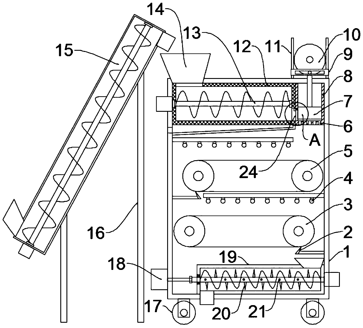
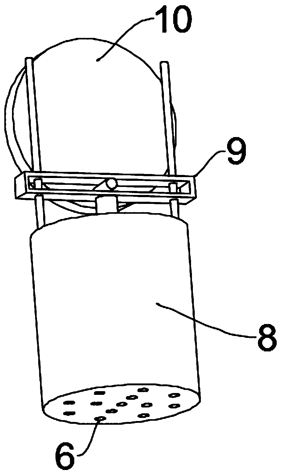
[0027] see Figure 1~3 , in the embodiment of the present invention, an automatic feeding type sludge treatment equipment includes a box body 1, a feeding unit, a drying unit and a discharging unit, and the feeding unit, the drying unit and the discharging unit are all installed in the box Inside the body 1, the drying unit is connected with the discharge unit. Rollers 17 are evenly installed on the bottom of the box 1. The rollers 17 are self-locking rollers to facilitate the movement of the device. The top left side of the box 1 is provided with a feeding Hopper 14, further, the left side of the box body 1 is equipped with a feeding auger 15 for lifting the sludge to the feeding hopper 14 through a mounting frame 16, and also includes an extrusion unit, which is located at the inlet Between the material unit and the drying unit and communicate with the two respectively, the feed unit includes a water-permeable cylinder 12 and a feed auger 13, the inner cavity on the left sid...

Embodiment 2

[0030] see Figure 4The difference between the embodiment of the present invention and embodiment 1 is that, in order to further increase the drying area of ​​the sludge, it also includes a cutting assembly, which includes a power motor 22 and a cutting blade 23, the The power motor 22 is installed on the upper part of the side wall of the casing 1, and the output shaft of the power motor 22 is fixed with a plurality of cutting blades 23 equidistant from the ring, and the cutting blades 23 are preferably mounted on the output shaft of the power motor 22 by screws. Above, the other end of the cutting blade 23 extends to the bottom of the extrusion chamber 8, and the side wall of the box body 1 is provided with a movement groove for the rotation of the cutting blade 23. When the extrusion block 7 is extruded, the power motor 22 drives the cutting blade 23 rotates so that strip-shaped sludge can be cut into small sections, thereby further increasing the drying area, drying more f...


PUM


Abstract

The invention discloses automatic feeding type sludge treatment equipment. The equipment comprises a box body, a feeding unit, a drying unit and a discharging unit; the feeding unit, the drying unit and the discharging unit are all installed in the box body; the drying unit communicates with the discharging unit; the equipment further comprises an extrusion unit; the extrusion unit is arranged between the feeding unit and the drying unit and communicates with the feeding unit and the drying unit; the extrusion unit comprises an extrusion bin, extrusion holes and a driving assembly for drivingthe extrusion block to reciprocate; the driving assembly comprises a driving motor, a disc, a movable rod and a connecting rod; the drying unit comprises a drying lamp, an upper conveying belt and a lower conveying belt; and the discharging unit comprises a discharging auger and crushing blades. The equipment is provided with the extrusion unit, and the driving unit drives the extrusion block to move up and down, then moisture in sludge can be extruded out, and meanwhile, sludge is continuously extruded out of the extrusion holes to be in a long strip shape, so that the sludge drying area is increased, and drying efficiency is improved.

Description

technical field [0001] The invention relates to the technical field of sludge treatment, in particular to automatic feeding sludge treatment equipment. Background technique [0002] Sludge treatment is the process of sludge reduction, stabilization and harmless treatment. The higher the degree of wastewater treatment, the more sludge residues are generated that need to be disposed of. Unless land treatment or sewage ponds are used to treat sewage, general sewage treatment plants must be equipped with sludge treatment facilities. For modern sewage treatment plants, the treatment and disposal of sludge has become the most complex and expensive part of the operation of the sewage treatment system. [0003] Existing sludge treatment equipment generally conducts sludge treatment by means of agitation drying, but due to the accumulation of sludge, the drying of the sludge is insufficient and the drying effect is reduced. Contents of the invention [0004] Embodiments of the p...

Claims


Application Information

Patent Timeline
Patent Type & Authority Applications(China)
IPC IPC(8): C02F11/125C02F11/13
CPCC02F11/125C02F11/13Y02A40/20
Inventor 陈娜娜
Owner 梁秀宜
Why Eureka
Try Eureka