Material disc containing rack for inner heating type heat pump drying device

A heat pump drying and internal heating technology, used in drying chambers/containers, dryers, etc., can solve the problem of inconvenient placement and removal of material trays, and achieve the effects of convenient removal, convenient use and reasonable structure

Inactive Publication Date: 2018-02-02
刘晓东
View PDF0 Cites 1 Cited by
  • Summary
  • Abstract
  • Description
  • Claims
  • Application Information

AI Technical Summary

Problems solved by technology

[0002] Heat pump drying uses vapor compression refrigeration technology to absorb heat energy from air or other waste heat resources. The thermal efficiency is more than three times that of electric heating. There is no pollutant emission during the heating and drying process. The production process is clean and safe, which is different from traditional coal and gas-fired Compared with electric heating and other drying devices, it has the advantages of high efficiency, energy saving, environmental friendliness, safety and reliability, high degree of automation, low production cost, and good product quality; however, the internal material storage rack of the existing heat pump drying device is only ordinary steel support It is not convenient to place and take out the material tray; in order to solve the above problems, it is necessary to develop a reasonable structure and easy-to-use internal heating heat pump drying device with a material tray rack

Method used


Image

  • Material disc containing rack for inner heating type heat pump drying device
  • Material disc containing rack for inner heating type heat pump drying device
  • Material disc containing rack for inner heating type heat pump drying device

Examples


Embodiment Construction

[0017] The present invention will be further described below in conjunction with the accompanying drawings. `

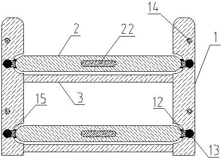
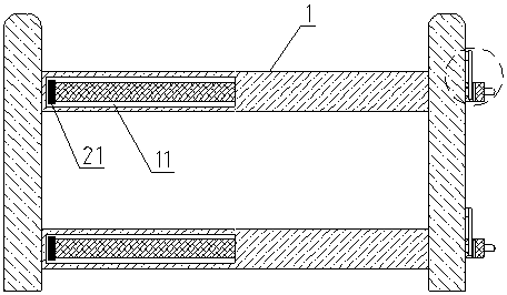
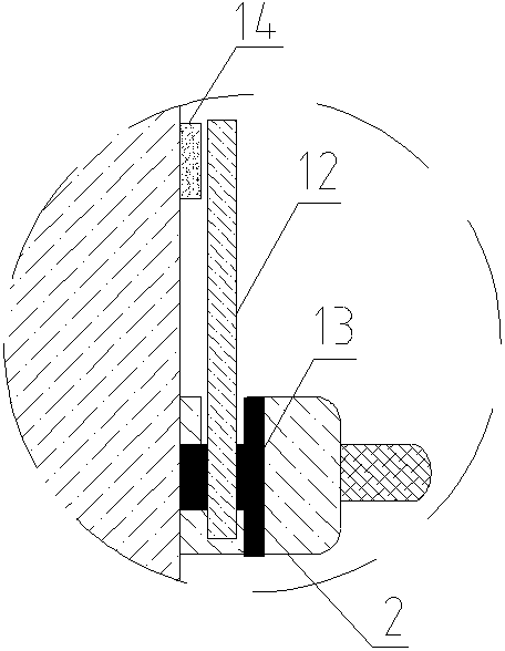
[0018] like figure 1 , figure 2 , image 3 , Figure 4 , Figure 5 , Image 6 Shown: a material tray placement rack for an internally heated heat pump drying device, including a fixed frame 1 and a sliding plate 2, the fixed frame 1 has two, and a connecting rod 3 is fixedly connected between them, and the sliding plate 2 It is located at the upper end of the connecting rod 3, and its two sides are connected vertically with the fixed frame 1 respectively. One end of the fixed frame 1 is provided with a strip-shaped through groove 11, and the outer surface of the other end is provided with an iron stopper 12. , the lower end of the iron stopper 12 is connected to the side of the fixed frame 1 through a connecting shaft 13, the iron stopper 12 can rotate around the connecting shaft 13, a magnet 14 is arranged above the connecting shaft 13, and the The magnet 14...


PUM


Abstract

The invention relates to a material tray placement frame for an internal heating type heat pump drying device, which includes a fixed frame and a sliding plate. There are two fixed frames, which are fixedly connected by a connecting rod. They are respectively connected to the fixed frame in a vertical shape. One end of the fixed frame is provided with a strip-shaped slot, and the outer surface of the other end is provided with an iron stopper. The lower end of the iron stopper is connected to the side of the fixed frame through a coupling shaft. It can rotate around the connecting shaft. There is a magnet on the top of the connecting shaft. The magnet is fixed on the side of the fixed frame. There is a strip plate matched with the strip-shaped through-slot structure, and a pull block is set in the middle of the other end, and the two sides of the end of the sliding plate close to the pull block are respectively symmetrically provided with stoppers matched with the iron stopper structure. Groove; the present invention has the advantages of reasonable structure and convenient use.

Description

technical field [0001] The invention belongs to the technical field of electric power equipment, and in particular relates to a material tray placement rack for an internal heating type heat pump drying device. Background technique [0002] Heat pump drying uses vapor compression refrigeration technology to absorb heat energy from air or other waste heat resources. The thermal efficiency is more than three times that of electric heating. There is no pollutant emission during the heating and drying process. The production process is clean and safe, which is different from traditional coal and gas-fired Compared with electric heating and other drying devices, it has the advantages of high efficiency, energy saving, environmental friendliness, safety and reliability, high degree of automation, low production cost, and good product quality; however, the internal material storage rack of the existing heat pump drying device is only ordinary steel support Rack, material tray is in...

Claims


Application Information

Patent Timeline
Patent Type & Authority Applications(China)
IPC IPC(8): F26B25/18
CPCF26B25/18
Inventor 刘晓东
Owner 刘晓东
Why Eureka
Try Eureka