RFID omnidirectional dynamic scanning antenna system

An antenna system, dynamic scanning technology, applied to antennas, antenna parts, antenna supports/installation devices, etc., can solve the problems of increasing the number of antennas, long coverage distance, power loss, etc., to reduce the number of antennas and cover long distances. , the effect of high gain

Active Publication Date: 2018-02-02
四川长虹技佳精工有限公司
View PDF4 Cites 9 Cited by
  • Summary
  • Abstract
  • Description
  • Claims
  • Application Information

AI Technical Summary

Problems solved by technology

Using the multi-antenna polling scheme, on the one hand, the number of antennas is increased, and on the other hand, each channel inevitably has a certain degree of power loss during the switching process
Therefore, there is no RFID omnidirectional dynamic scanning antenna system with high gain, long coverage distance, wide coverage, effective elimination of coverage blind spots, and a significant reduction in the number of antennas in the prior art.

Method used


Image

  • RFID omnidirectional dynamic scanning antenna system
  • RFID omnidirectional dynamic scanning antenna system
  • RFID omnidirectional dynamic scanning antenna system

Examples


Embodiment 1

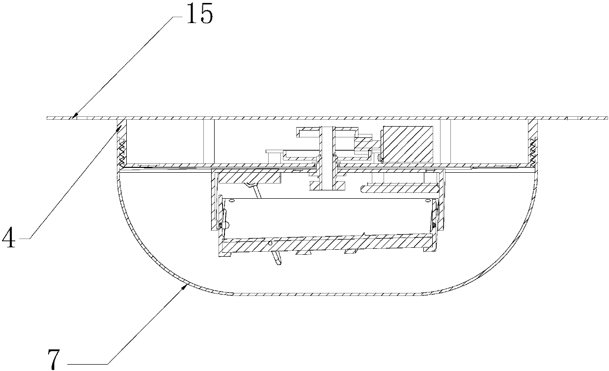
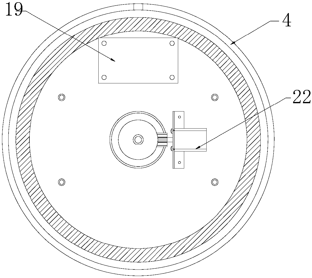
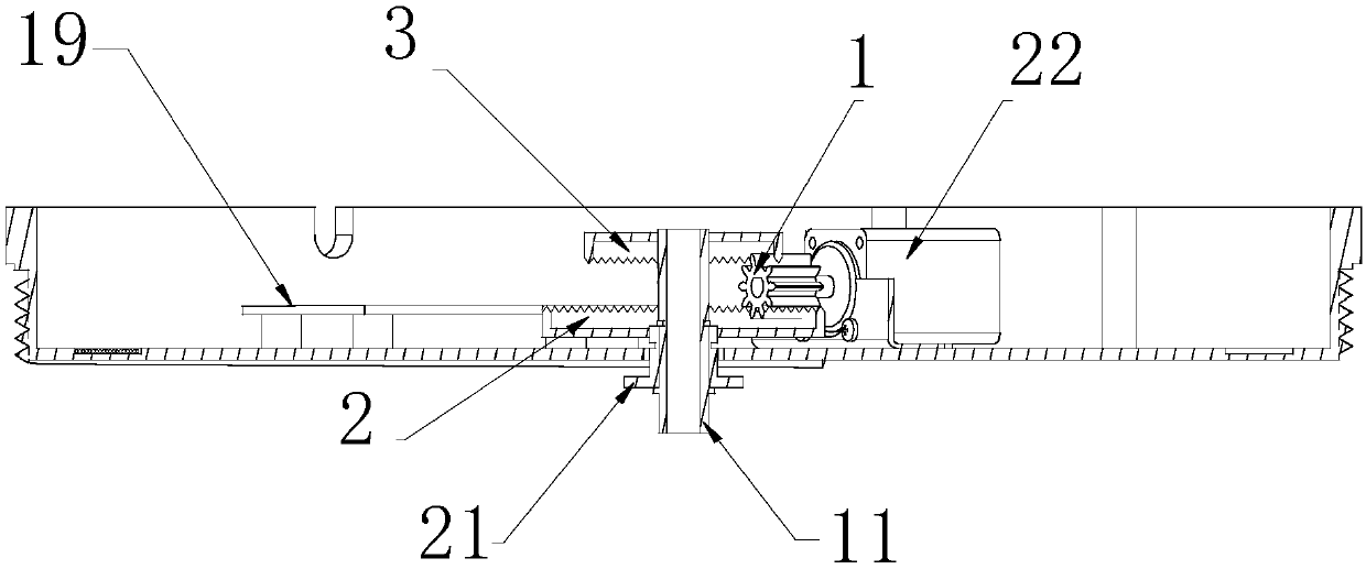
[0035] like figure 1 In this embodiment shown, the external structure of the present invention consists of a mounting plate 15 , an antenna base 4 and an antenna protective cover 7 . The antenna base 4 is connected with the mounting plate 15 through the fixing screw holes; the mounting plate 15 is fixed on the top of the use area through the bolt holes, such as positions such as the top of the warehouse; to protect its internal structure. like figure 2 , image 3 As shown, the antenna base 4 is provided with an AC power input port.

Embodiment 2

[0037] In the present embodiment, the electrical part of the application is arranged on two circuit boards, i.e. circuit board A18 and circuit board A19, the RFID antenna power supply and the driving power are respectively located on the circuit board A18 and circuit board A19, and the drive system adopts a stepper motor 22 . The circuit board A19 conducts magnetic field coupling with the coil A through the coil B, and transmits electric energy to the coil A by means of electromagnetic induction; the circuit board A19 communicates with the circuit board A18 through the near-field communication module, receives the control command sent by the circuit board A18, and returns Corresponding status information; the circuit board A19 drives the stepper motor 22 to rotate; when the read-write system is not working, the circuit board A18 sends a charging command to the circuit board A19 through the wireless communication module, and the circuit board A19 stops the rotation of the steppe...

Embodiment 3

[0039] In the present embodiment, on circuit board A19, be provided with microprocessor control system; Also be provided with stepper motor 22 drive circuits; Also be provided with wireless charging primary coil and control circuit thereof, what adopted in the present embodiment is ZigBee Short distance wireless communication module. In actual use, other wireless communication methods such as bluetooth and radio frequency may also be used. In the RFID read-write module 10 in this embodiment, the circuit board A18 is arranged on the antenna rotating base 5 . The storage battery 8 is pasted on the circuit board A18 by double-sided tape, and connected with the circuit board A18 by cables. A wireless charging circuit is arranged on the circuit board A18 and is connected to the wireless charging secondary coil A. When the antenna system is on standby, the circuit board A18 sends a charging instruction to the circuit board A19 through the short-distance wireless communication modu...


PUM


Abstract

The invention discloses a RFID omnidirectional dynamic scanning antenna system and particularly relates to a RFID omnidirectional dynamic scanning antenna system in the field of RFID antenna mechanisms. The RFID omnidirectional dynamic scanning antenna system of the invention comprises a power supply, a controller, a driving system, a RFID directional antenna, a RFID read and write module, a rotating motion transmission mechanism, a reciprocating swing transmission mechanism, an antenna base, an antenna rotating seat and an antenna fixation support; the controller is connected with the drivingsystem; the controller is connected with a data communication port of the RFID read and write module; an output terminal of the rotating motion transmission mechanism is connected with the antenna rotating seat ; the RFID directional antenna is installed on the antenna fixation support. The RFID omnidirectional dynamic scanning antenna system has high gain, long coverage distance, wide coverage range, and can effectively eliminate blind area of coverage and significantly reduce the number of antennas.

Description

technical field [0001] The invention relates to an RFID omnidirectional dynamic scanning antenna system, in particular to an RFID omnidirectional dynamic scanning antenna system related to the field of RFID antenna mechanisms. Background technique [0002] At present, RFID technology is widely used in material inventory and management to realize intelligent management, does not require contact identification, can penetrate various media and read, and the reading speed is fast. Antennas widely used in RFID systems are directional antennas and omnidirectional antennas. But omnidirectional antennas have limited gain and low sensitivity. However, due to the small main lobe angle of the radiation direction of the antenna, generally between 40° and 60°, the directional antenna often cannot cover the entire area that needs to be inventoried. Therefore, the commonly used RFID reading systems generally need to configure multiple antennas and poll work to cover the entire area that ...

Claims


Application Information

Patent Timeline
Patent Type & Authority Applications(China)
IPC IPC(8): H01Q3/08H01Q1/22G06K7/10
CPCH01Q1/2216H01Q3/08G06K7/10316Y02D30/70
Inventor 马致远
Owner 四川长虹技佳精工有限公司
Why Eureka
Try Eureka