
Clock synchronization device for positioning base station and synchronization method thereof

A technology for clock synchronization and base station positioning, which is applied in time division multiplexing systems, electrical components, wireless communications, etc. cost reduction effect

Pending Publication Date: 2018-02-02
丰翼科技(深圳)有限公司
View PDF0 Cites 2 Cited by
  • Summary
  • Abstract
  • Description
  • Claims
  • Application Information

AI Technical Summary

Problems solved by technology

[0003] However, the wireless self-synchronization system is difficult to develop and has a long cycle. It needs to rely on the GPS positioning clock to keep the clock of the UWB base station synchronized. When it is disturbed by the outside world, it is prone to inaccurate positioning.
The commonly used wireless self-synchronization system starts the 8MHZ clock through the PLL clock generation / distribution chip. The price of the chip is high, which greatly increases the production cost.

Method used


Image

  • Clock synchronization device for positioning base station and synchronization method thereof
  • Clock synchronization device for positioning base station and synchronization method thereof
  • Clock synchronization device for positioning base station and synchronization method thereof

Examples


Embodiment 1

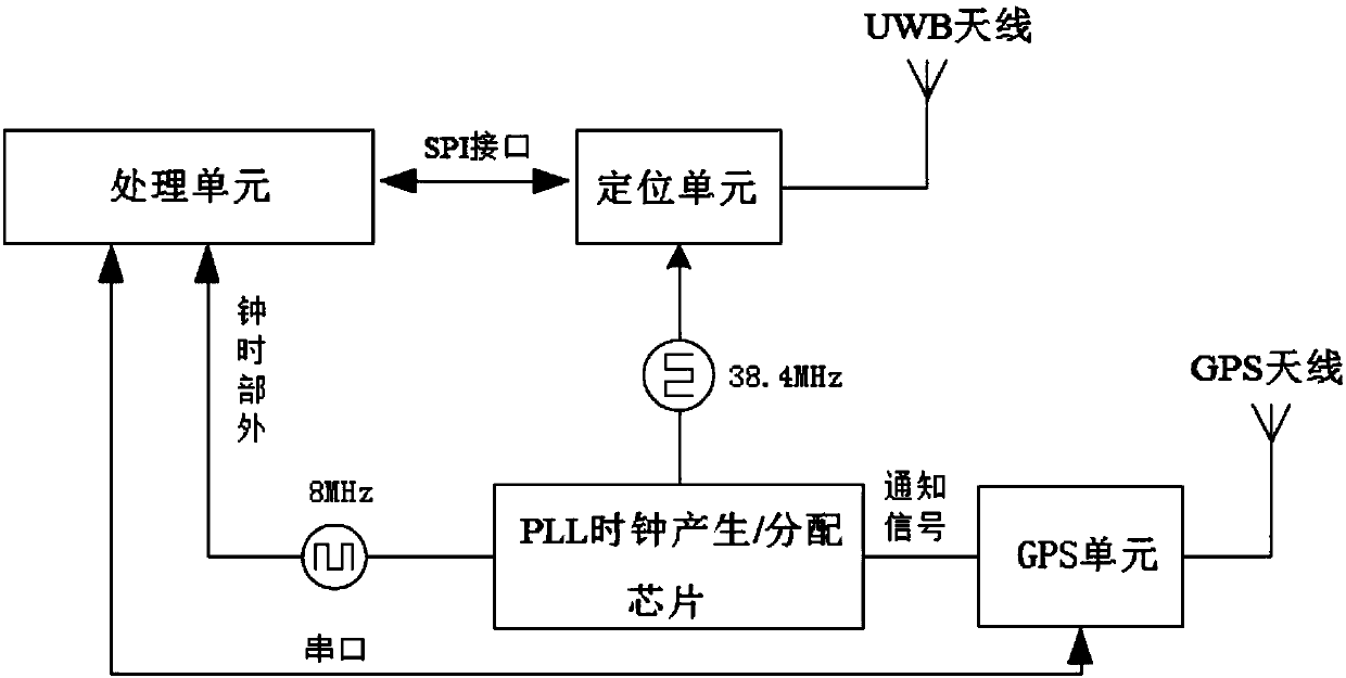
[0039] like figure 1 As shown, the commonly used wireless self-synchronization system, in which, the GPS unit LEA-6T is connected to the PLL clock generation / distribution chip through the PPS port to transmit the notification signal (PPS signal), and the PLL clock generation / distribution chip is connected to the processing unit signal of the STM32F series Connection, the output is the 8MHZ clock required by the processing unit, the PLL clock generation / distribution chip outputs the 38.4MHZ clock required by the UWB chip DW1000, the UWB chip DW1000 is connected to the UWB antenna, the UWB chip DW1000 is connected to the processing unit through the SPI interface, and the processing unit , The UWB chip is connected through the signal, the GPS unit LEA-6T is connected with the processing unit through the serial port, and the GPS unit LEA-6T is connected with the GPS antenna.

[0040] The wireless self-synchronization system is difficult to develop and has a long cycle. It needs to...

Embodiment 2

[0073] The features of this embodiment that are the same as those of Embodiment 1 will not be described in detail. The features of this embodiment that are different from Embodiment 1 are:

[0074] MCU adopts STM32F405.

Embodiment 3

[0076] The features of this embodiment that are the same as those of Embodiment 1 will not be described in detail. The features of this embodiment that are different from Embodiment 1 are:

[0077] MCU adopts STM32F407.


PUM


Abstract

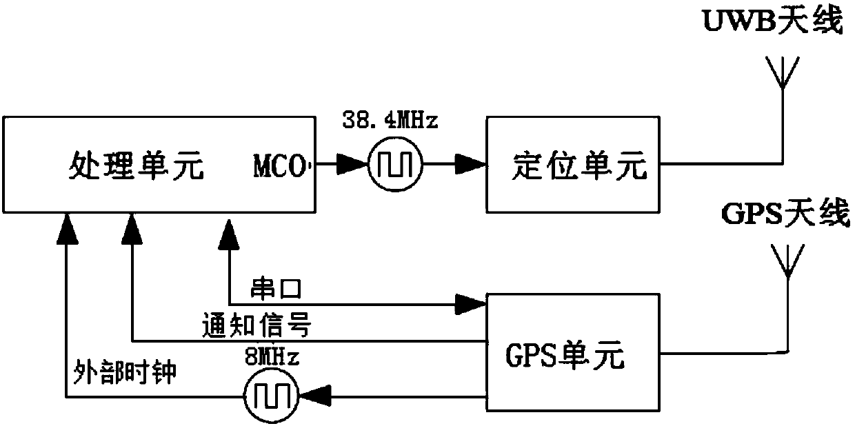
The invention relates to a clock synchronization device for a positioning base station and a synchronization method thereof. The clock synchronization device for the positioning base station comprisesa GPS unit used for positioning and outputting a first clock signal; a processing unit used for receiving the first clock signal and outputting a second clock signal, wherein the first clock signal is synchronized with the GPS unit; and a positioning unit used for receiving the second clock signal, wherein the second clock signal is in clock synchronization with the positioning unit. The clock synchronization device for the positioning base station provided by the invention realizes the clock synchronization of the GPS unit and the positioning unit; if the clock precision is the same, then the clock of each positioning unit of the positioning base station is synchronous, and the clock synchronization device does not need to depend on a GPS positioning clock to keep the clock of the positioning base station to be synchronous like the prior art, and an expensive PLL clock is not needed to be used to generate / distribute chips, so that the cost is greatly reduced; and besides, the structure is simple and the positioning is accurate.

Description

technical field [0001] The invention relates to the field of clock synchronization, in particular to a positioning base station clock synchronization device and a synchronization method thereof. Background technique [0002] With the improvement of people's requirements for positioning accuracy, UWB positioning technology is more and more popular because of its accuracy up to centimeters, and some indoor positioning: such as factory automation management, prison security management, robotics and other fields The needs are also increasing. obvious. In view of the uniqueness of its positioning system, a UWB positioning system includes at least one positioning tag (Tag) + 4 positioning base stations (Anchor) + positioning server + router (can be wired or wireless, and the positioning base station provides wired or wireless information through this router) connection and location server communication). The working principle is: the positioning tag (Tag) sends a beacon signal i...

Claims


Application Information

Patent Timeline
IPC IPC(8): H04J3/06H04W88/08
CPCH04J3/0685H04W88/08
Inventor 杨久洲
Owner 丰翼科技(深圳)有限公司
Learn More