Automatic core taking mechanism and core taking method

An automatic, sand core technology, applied in the direction of cores, casting molding equipment, casting molds, etc., can solve the problem of the shape of the mud core requiring high sand box retreat space, etc., and achieve the effect of simple structure, simple operation and convenient replacement.

Active Publication Date: 2018-02-06
CRRC CHANGZHOU AUTO PARTS CO LTD +1
View PDF5 Cites 5 Cited by
  • Summary
  • Abstract
  • Description
  • Claims
  • Application Information

AI Technical Summary

Problems solved by technology

[0007] The object of the present invention is: aiming at the defects in the prior art, an automatic coring mechanism is proposed, and a coring method is provided at the same time. The coring mechanism is firm and reliable, with high core precision and simple operation, which solves the problem of traditional hooks. The core setting mechanism has the disadvantages of high requirements on the shape of the core and the need to reserve a concession space on the sand box

Method used


Image

  • Automatic core taking mechanism and core taking method
  • Automatic core taking mechanism and core taking method
  • Automatic core taking mechanism and core taking method

Examples


Embodiment 1

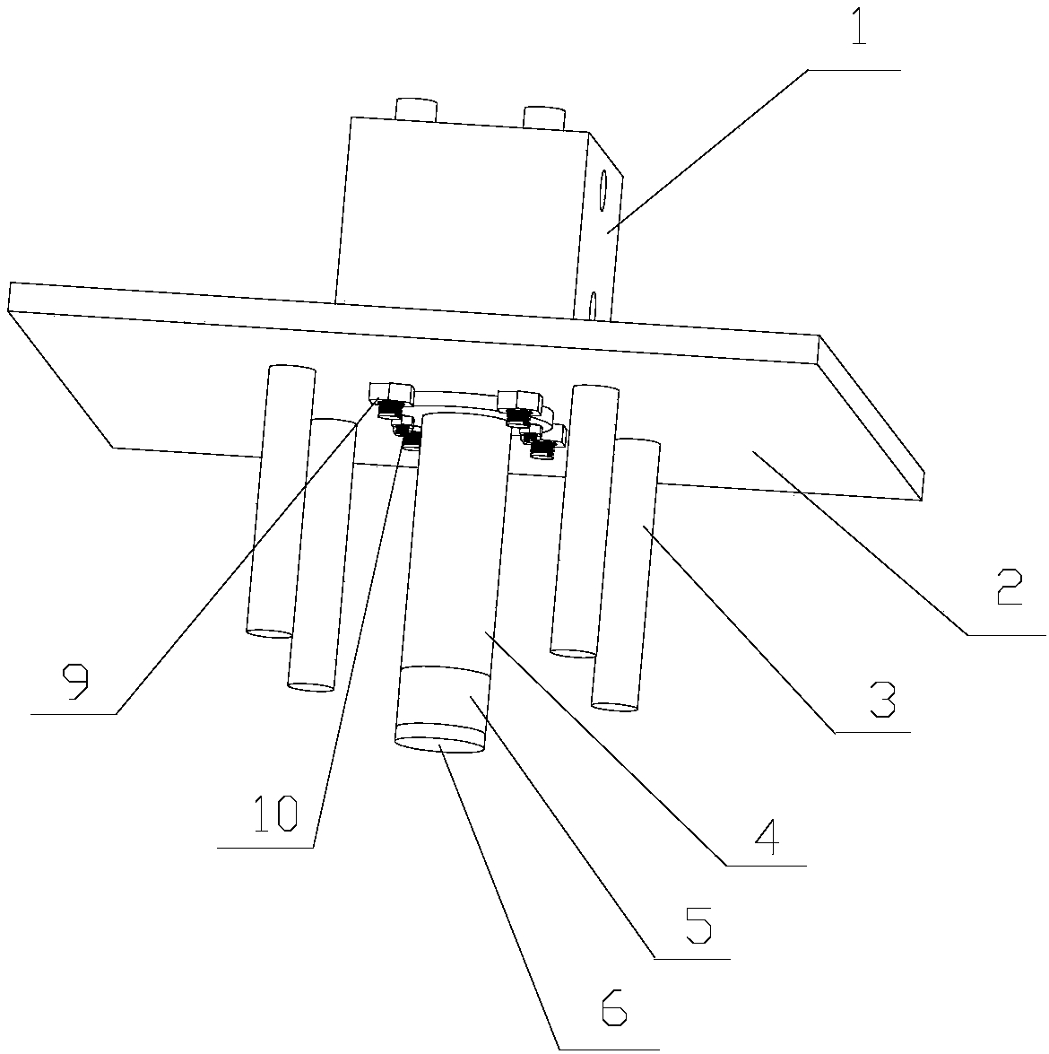
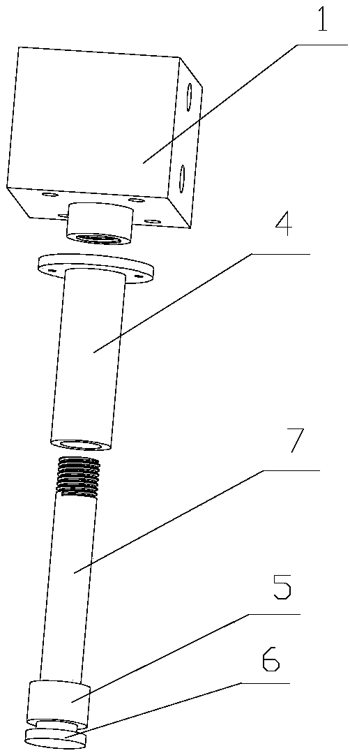
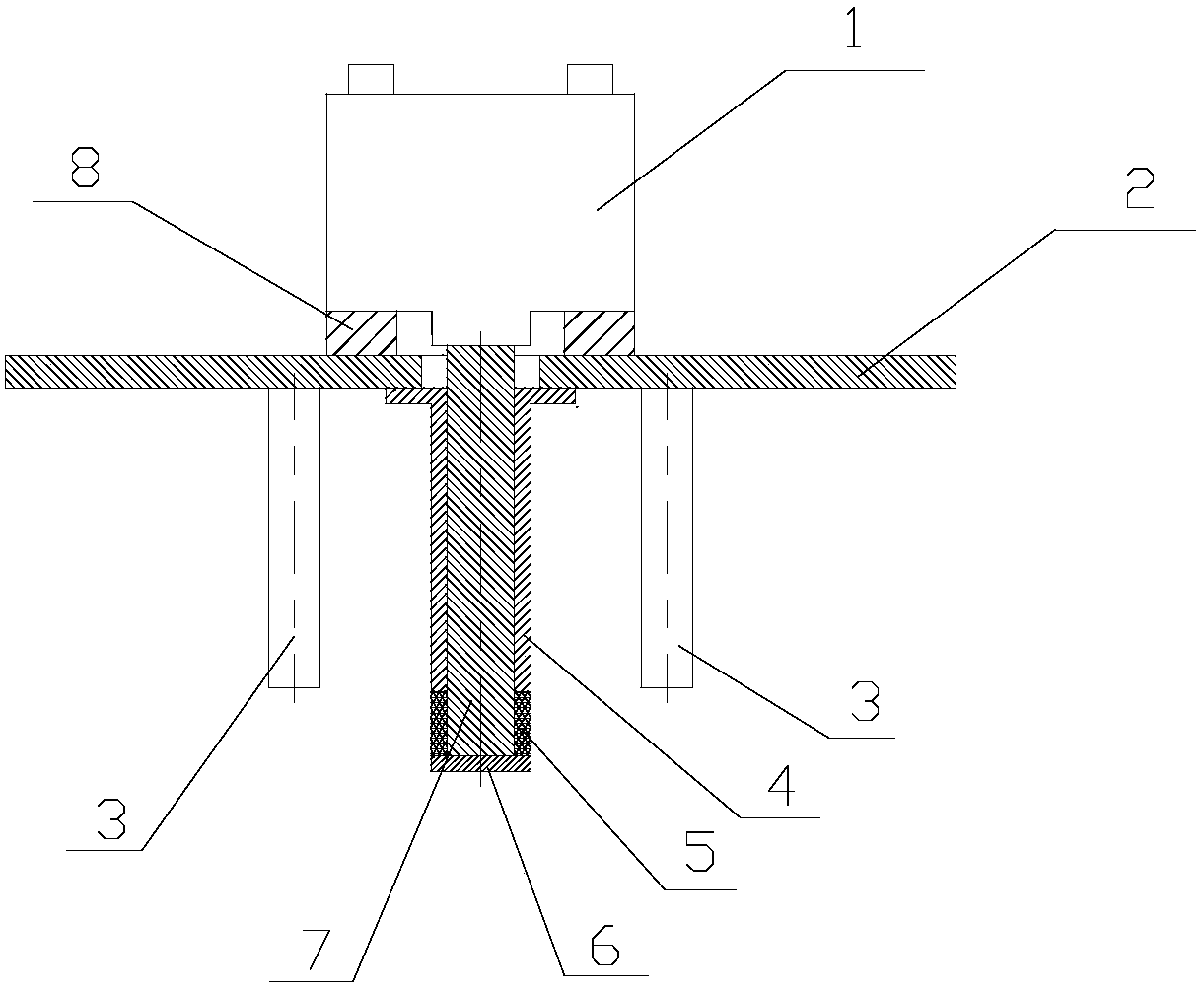
[0039] The automatic core lowering mechanism of the present embodiment has a structure such as figure 1 , figure 2 with image 3 As shown, it includes a cylinder 1, a fixed plate 2, a limit rod 3, a guide sleeve 4, a rubber sleeve 5, a limit block 6 and a guide rod 7. The upper end surface of the fixed plate 2 is provided with a cylinder 1, and the cylinder 1 acts as a driving guide. The effect of rod 7 moving up and down, between cylinder 1 and fixed plate 2, be provided with pad 8 that plays the role of supporting cylinder 1, pad 8 is provided with four screw holes 1, is provided with screw rod 1 9 with screw hole 1, cylinder 1 is installed on the fixed plate 2 through four screw rods 9 passing through the pad 8; the lower end surface of the fixed plate 2 is provided with a guide sleeve 4 and four limit rods 3, and the four limit rods 3 are evenly distributed around the guide sleeve 4 , and set vertically downward on the fixed plate 2, the limit rod 3 and the fixed plate ...


PUM


Abstract

The invention relates to an automatic core taking mechanism which comprises a cylinder, a fixed plate, limiting rods, a guide sleeve, a rubber sleeve, a limiting block and a guide rod. The guide rod passes through a guide hole on the fixed plate to be connected with a piston rod of the cylinder; the guide rod is sleeved with the guide sleeve; the limiting block is arranged at the bottom end of theguide rod; the rubber sleeve connected with the guide sleeve is arranged on the guide rod and above the limiting block; a plurality of vertical downward limiting rods are arranged on the fixed plateand around the guide sleeve. The automatic core taking mechanism has the advantages that the automatic core taking mechanism is simple in structure and ingenious in design; the rubber sleeve is adopted to expand a locking mechanism, and in the clamping process, the guide rod is directly lifted up by the cylinder to compress the rubber sleeve to generate an expansion force, so that the rubber sleeve is in interference fit with a matching hole of a core, thereby implementing clamping. Therefore, the core taking mechanism disclosed by the invention is free to advance or retreat in the core takingprocess without reserving a retreating space in a sand mold, so that the defects of a conventional lifting hook core taking mechanism are overcome, and automatic core taking for a KW line large-sizedcore is implemented.

Description

technical field [0001] The invention relates to a core setting device used on an automatic production line, in particular to an automatic core setting mechanism and a core setting method for realizing the purpose of automatic core setting in the foundry industry, and belongs to the technical field of fixture machinery. Background technique [0002] Casting green sand automation line, taking KW line as an example, belongs to the automatic production line with larger sand box in the casting line. The size of the sand box is 1300×900×400 / 300mm. This molding line is suitable for the production of complex and large castings. The mud cores involved in the production process are also relatively large, and conventional manual handling and core setting are difficult to achieve, and core setting mechanisms are often used. Now the KW line coring is mostly using the hook mechanism, that is, a hanging hole is reserved on the mud core, and the hook is used to hook the hanging hole when ta...

Claims


Application Information

Patent Timeline
IPC IPC(8): B22C9/10
CPCB22C9/108
Inventor 佘恺李赵王凯赵文俊
Owner CRRC CHANGZHOU AUTO PARTS CO LTD
Why Eureka
Try Eureka