Log conveying device

A technology for conveying devices and round logs, which is applied in the direction of conveyors, transportation, packaging, packaging, etc., can solve the problems of large-scale machinery such as high energy consumption, high labor intensity, and poor safety, and achieve high energy consumption, strong continuity, and The effect of simple structure

Inactive Publication Date: 2018-02-06
湖州跃盛农业科技有限公司
View PDF6 Cites 1 Cited by
  • Summary
  • Abstract
  • Description
  • Claims
  • Application Information

AI Technical Summary

Problems solved by technology

Using steel wire ropes and hooks to hoist round materials such as logs is labor-intensive, time-consuming, low-efficiency, and poor-safety
Especially for the short-distance handling of round logs, the use of large-scale machinery consumes a lot of energy, and the use of manual handling is labor-intensive.

Method used


Image

  • Log conveying device
  • Log conveying device
  • Log conveying device

Examples


Embodiment 1

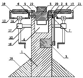
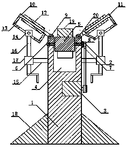
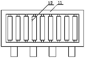
[0015] A log conveying device of the present invention includes a rectangular parallelepiped frame body 1, a transmission chain 2 and a drive motor 3. The top of the rectangular parallelepiped frame body 1 is provided with a longitudinal groove 4, and more than two grooves 4 are arranged in the grooves 4 The rotating roller 5, the shafts 6 at both ends of the rotating roller 5 are all mounted on the side wall of the groove 4 through bearings, and the outer circumference of the rotating roller 5 is fixedly installed with more than one axial blade 19, the rotating roller 5 The extension of the shaft 6 at one end is provided with a transmission wheel 7 and is connected by a transmission chain 2. One of the extensions of the shaft 6 is provided with a driving wheel 8 which is connected to the drive motor 3 fixed on the rectangular parallelepiped frame 1. The left side of the top groove 4 of the body 1 is movably connected to the left frame 10 through a first shaft 9 and the right si...

Embodiment 2

[0017] A log conveying device of the present invention includes a rectangular parallelepiped frame 1, a transmission chain 2 and a drive motor 3. The top of the rectangular parallelepiped frame 1 is provided with a longitudinal groove 4, and more than two grooves 4 are arranged The rotating roller 5, the shafts 6 at both ends of the rotating roller 5 are all mounted on the side wall of the groove 4 through bearings, and the outer circumference of the rotating roller 5 is fixedly installed with more than one axial blade 19, the rotating roller 5 The extension part of the shaft 6 at one end is provided with a transmission wheel 7 and is connected by a transmission chain 2. One of the extension parts of the shaft 6 is provided with a driving wheel 8 which is connected to the drive motor 3 fixed on the cuboid frame 1. The cuboid frame The left side of the top groove 4 of the body 1 is movably connected to the left frame 10 through a first shaft 9 and the right side of the top groove...


PUM


Abstract

The invention discloses a log conveying device, and belongs to the field of woodware machining. The log conveying device comprises a cuboid frame, a transmission chain and a driving motor, a longitudinal groove is formed in the top of the cuboid frame of the log conveying device, two or more rotary rolls are evenly arranged in the groove, and shaft rods at the two ends of the rotary rolls are mounted on the side walls of the groove through bearings. One or more axial blades are fixedly mounted on the periphery of each rotary roll, a transmission wheel is arranged on an extending part of the shaft rod at one end of each rotary roll, the transmission wheels are connected through the transmission chain, and a driving wheel is arranged on the extending part of one shaft rod and is in transmission connection with the driving motor fixed to the cuboid frame. The left side of the cuboid frame is in matched connection with a left frame, the right side of the cuboid frame is in matched connection with a right frame, and roll wheels are mounted in the left frame and the right frame. The log conveying device is simple in structure, reasonable in design, convenient to use, especially suitablefor short-distance carrying of logs, low in energy consumption, high in continuity and high in safety, the labor intensity is reduced, and the work efficiency is improved.

Description

Technical field [0001] The invention belongs to the field of wood product processing, and in particular relates to a log conveying device. Background technique [0002] In the field of wood product processing, round wood is a relatively common raw material for processing. Most of the wood products are processed from round wood. The current round wood handling usually uses engineering machinery, such as truck cranes, truck-mounted cranes, etc. It is mainly equipped with wire rope and hook. When hoisting round materials such as logs, the operator needs to carefully bundle them with steel wire ropes, and then hang the hooks for lifting. The use of steel wire ropes and hooks to hoist round wood and other round materials requires high labor intensity, long time, low efficiency and poor safety. Especially for round logs in short-distance transportation, large-scale machinery consumes more energy and manual transportation is labor-intensive. Summary of the invention [0003] In view o...

Claims


Application Information

Patent Timeline
Patent Type & Authority Applications(China)
IPC IPC(8): B65G13/12B65G13/07
CPCB65G13/07B65G13/12B65G2201/0282B65G2207/08
Inventor 陈笑音
Owner 湖州跃盛农业科技有限公司
Why Eureka
Try Eureka