
Anti-oxidation device for enameled wire production equipment

A production equipment, anti-oxidation technology, applied in heat treatment equipment, furnaces, manufacturing tools, etc., can solve the problems of copper wire oxidation, the anti-oxidation effect is not very good, etc.

Pending Publication Date: 2018-02-06
湖州华上电工科技股份有限公司
View PDF1 Cites 1 Cited by
  • Summary
  • Abstract
  • Description
  • Claims
  • Application Information

AI Technical Summary

Problems solved by technology

[0004] However, the effect of anti-oxidation only through water vapor is not very good, because water vapor will generate oxygen, which will oxidize the copper wire

Method used


Image

  • Anti-oxidation device for enameled wire production equipment

Examples


Embodiment Construction

[0018] The present invention will be described in further detail below in conjunction with the accompanying drawings.

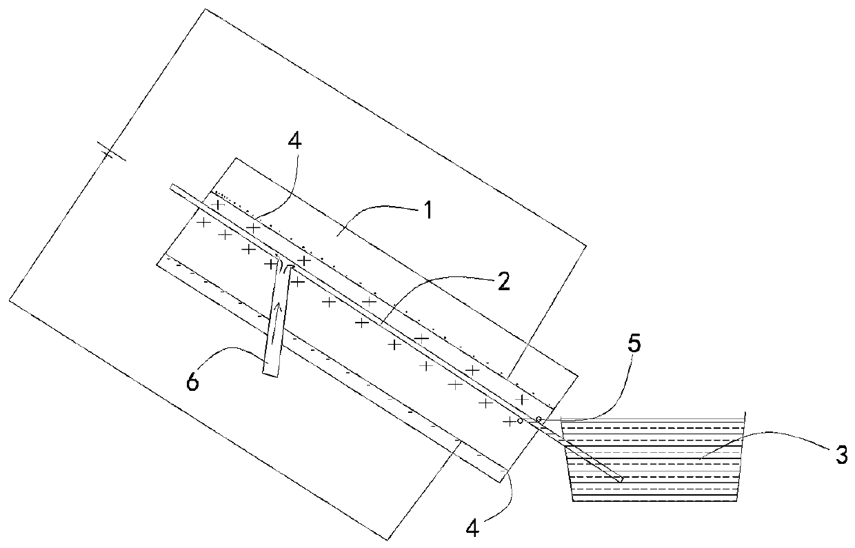
[0019] Such as figure 1 The anti-oxidation device of the enameled wire production equipment shown includes an annealing furnace 1 and an annealing pipeline 2 running through it. A water tank 3 is arranged at the copper wire outlet end of the annealing pipeline 2. Two iron plates 4 and one iron plate are embedded in the annealing furnace 1. The plate 4 is connected to the positive pole of the power supply, another iron plate 4 is connected to the negative pole of the power supply, and the iron plate 4 connected to the positive pole of the power supply is close to the annealing pipeline 2 .

[0020] On the outer wall of the annealing pipeline 2 and at the bottom of the annealing furnace 1, an electric heating tube 5 is arranged. The annealing pipeline 2 passes through the annealing furnace 1 and is inserted into the water tank 3 . The installation height of t...


PUM


Abstract

The invention discloses an anti-oxidation device for enameled wire production equipment, which relates to the technical field of enameled wire production. The anti-oxidation device comprises an annealing furnace and an annealing pipeline penetrating through the annealing furnace, and a water tank is arranged at the copper wire outlet end of the annealing pipeline. The anti-oxidation device is characterized in that two iron plates are embedded in the annealing furnace, one iron plate is connected to the anode of a power supply, the other iron plate is connected to the cathode of the power supply, and the iron plate which is connected to the anode of the power supply is close to the annealing pipeline. The objective of the invention is to put a copper wire into an environment which is constantly filled up with positive charges, so that substances capable of easily oxidizing the copper wire in the outside environment can directly react with the positive charges wrapping the periphery of the copper wire.

Description

technical field [0001] The invention relates to the technical field of enameled wire production, in particular to an anti-oxidation device for enameled wire production equipment. Background technique [0002] At present, during annealing in the production of enameled wires, steam is needed to prevent the oxidation of bare copper wires, and heat is needed for the generation of steam. At present, the steam in the existing annealing furnace is generated by a steam generating device, or heated by an electric heating tube wound outside the annealing tube. This method consumes a lot of power, so the production cost is very high. However, the existing annealing furnace body is usually placed at an angle of 5 to 15°. Due to the small inclination angle, when the copper wire passes through the annealing tube, it is prone to scratches under the action of gravity. Due to uneven heating, the steam supply fluctuates. This causes quality problems such as beading, scratches, uneven color, ...

Claims


Application Information

Patent Timeline
IPC IPC(8): C21D1/04C21D9/56C22F1/08H01B13/00
CPCH01B13/00C21D1/04C21D9/561C21D9/562C22F1/08
Inventor 沈林华
Owner 湖州华上电工科技股份有限公司
Learn More