

Impeller type axial and circumferential compound impactor
An impeller-type, impactor technology, applied in drilling equipment, earth-moving drilling, driving devices for drilling in wellbore, etc., can solve the problems of well wall friction, affecting the drilling speed, damage to the drill bit, etc., and achieve circumferential positive impact High force, high energy conversion efficiency, elimination of stick-slip and sticking effects
- Summary
- Abstract
- Description
- Claims
- Application Information
AI Technical Summary
Problems solved by technology
Method used
Image

Examples
Embodiment Construction
[0022] The present invention will be described in detail below in conjunction with the accompanying drawings and embodiments.
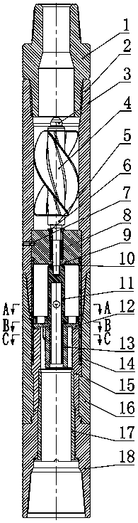
[0023] Referring to the accompanying drawings, the impeller-type axial and circumferential composite impactor is composed of a conversion joint 1, a motor assembly and an impact assembly. The rear end of the motor assembly is connected to the conversion joint 1 through threads, and the front end is connected to the impact assembly; the motor The assembly includes impeller housing 2, lock nut 3, impeller 4, impeller shaft 5, bearing cover 6, screw 7, string bearing 8 and guide tube 10, and impeller 4 is installed on impeller shaft 5 through spline connection , and use the lock nut 3 to axially fix, the front section of the impeller shaft 5 is installed in the guide tube 9, and the string bearing 8 is installed inside the guide tube 9, and the bearing end cover 6 is installed on the end surface of the guide tube 9 through threaded connection , there are...
PUM
 Abstract
Description
Claims
Application Information