Exposure device and method

An exposure device and exposure method technology, applied in the field of photolithography, can solve the problems of inconsistent deformation of flexible substrates, poor exposure accuracy, etc.

Active Publication Date: 2018-02-06
SHANGHAI MICRO ELECTRONICS EQUIP (GRP) CO LTD
View PDF6 Cites 8 Cited by
  • Summary
  • Abstract
  • Description
  • Claims
  • Application Information

AI Technical Summary

Problems solved by technology

[0004] The present invention provides an exposure device and method to solve the problem of poor ex...

Method used


Image

  • Exposure device and method
  • Exposure device and method
  • Exposure device and method

Examples


Embodiment 2

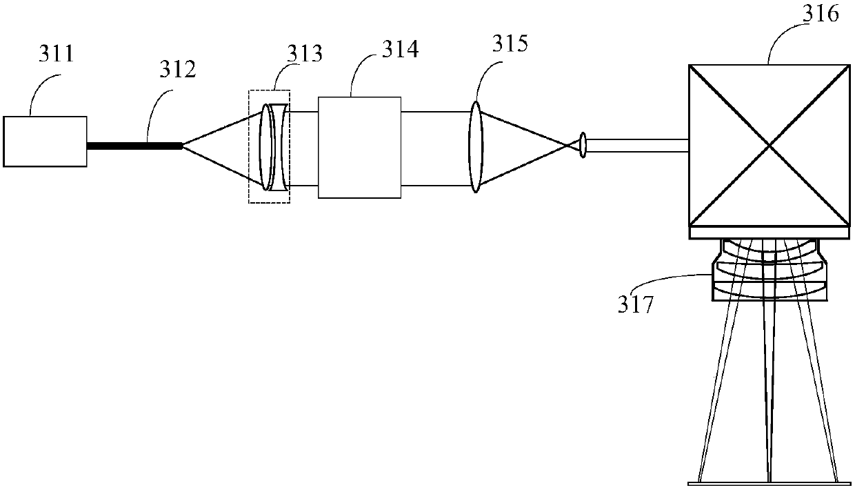
[0082] Such as Figure 10 As shown, different from Embodiment 1, in this embodiment, the first exposure system 31 and the third exposure system 41 include a first light source 311, a beam expander assembly 315, a shaping assembly 314, a scanning Vibrating mirror assembly 316 and field lens 317; The first light source 311 is a laser light source, and the collimated light beam sent is adjusted by the beam expander assembly 315 after the diameter of the beam, and then enters the shaping assembly 314 to form the required spot shape, and the light spot shape can be It is a rectangular spot, and of course it can also be in other shapes. The shaping component 314 is DOE (Diffractive Optical Elements, diffractive optical element) or ROE (refractive Optical Elements, refractive optical element).

Embodiment 3

[0084] Such as Figure 11 As shown, different from the above-mentioned embodiment 1-2, the first exposure system 31 and the third exposure system 41 include a first light source 311, a beam expander assembly 315, a shaping assembly 314, and a focusing lens 318 arranged in sequence along the optical path. , the objective lens 319 and the scanning galvanometer assembly 316, the first light source 311 is a laser light source, the output collimated beam passes through the beam expander assembly 315 to adjust the beam diameter, and then enters the shaping assembly 314 to form the required spot shape, and then adjusts The focus lens 318 adjusts the focus of each point of view in the entire field of view, so that the light beams of each point of view are focused on the plane, and finally after being imaged by the objective lens 319, it is reflected to the focal plane by the scanning galvanometer assembly 316, and the flexible substrate 1 to make the exposure. The shape of the light ...


PUM


Abstract

The invention discloses an exposure device and an exposure method. The device comprises a flexible substrate and a reel-to-reel transmission system, wherein the reel-to-reel transmission system is used for transmitting and fixing the flexible substrate; the exposure device also comprises a frontal-surface exposure system and a back-surface exposure system which are symmetrical about the axial direction of the flexible substrate, measurement systems which are corresponding to the frontal surface and the back surface of the flexible substrate respectively, and a master control system which is connected with the reel-to-reel transmission system, the frontal-surface exposure system, the back-surface exposure system and the measurement systems respectively. Through arranging the frontal-surfaceexposure system and the back-surface exposure system, the frontal surface and the back surface in the flexible substrate are exposed respectively; not only is the exposure efficiency improved; but also two different exposure systems are arranged respectively in the frontal-surface exposure system and the back-surface exposure system at the same time to realize the coarse exposure and the correction exposure on different exposed graphs on the flexible substrate; the exposure device can adapt to different deformation amounts and the exposure precision is greatly improved.

Description

technical field [0001] The present invention relates to the technical field of photolithography, in particular to an exposure device and method. Background technique [0002] In the roll-to-roll (English: roll to roll) process, the processing substrate is a flexible substrate, and there are usually multi-layer exposure patterns on the flexible substrate. During the flattening process of the flexible substrate, each flattening operation will cause the flexible substrate to have different Therefore, the traditional proximity exposure cannot meet the exposure accuracy. [0003] Such as figure 1 As shown, it is a structural diagram of a commonly used proximity exposure system, including a light source 1', an illumination mirror group 2', a mask 3', and a flexible substrate 4'. The light beam emitted by the light source 1' is irradiated onto the mask 3' through the illumination lens group 2', and the pattern on the mask 3' is transferred to the flexible substrate 4'. Wherein t...

Claims


Application Information

Patent Timeline
IPC IPC(8): G03F7/20
CPCG03F7/70466G03F7/70633
Inventor 陈勇辉蓝科陈文枢戈亚萍
Owner SHANGHAI MICRO ELECTRONICS EQUIP (GRP) CO LTD
Why Eureka
Try Eureka