
Video acquisition device and acquisition method using the same

The technology of a video acquisition device and acquisition method is applied to parts of color TVs, parts of TV systems, TVs, etc., and can solve problems such as inability to collect high frame rate videos, difficult requirements for video collection, and bulky optical lenses.

Active Publication Date: 2019-11-08
SUMAVISION TECH CO LTD
View PDF5 Cites 0 Cited by
  • Summary
  • Abstract
  • Description
  • Claims
  • Application Information

AI Technical Summary

Problems solved by technology

Under the premise of high resolution, in order to achieve a wide viewing angle, it can be realized by horizontally rotating the line array sensor, but because the optical lens is very heavy, the rotation can only be performed at a low speed. This system can only collect static images and cannot collect high frames. rate video
[0004] To sum up, it is difficult for the existing technology to meet the video capture requirements of wide viewing angle and high resolution at the same time

Method used


Image

  • Video acquisition device and acquisition method using the same
  • Video acquisition device and acquisition method using the same
  • Video acquisition device and acquisition method using the same

Examples


Embodiment 1

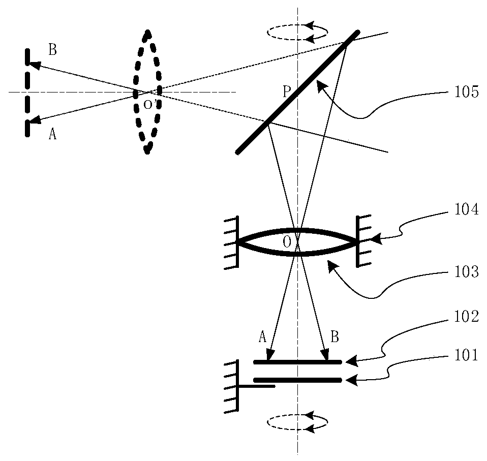
[0048] figure 1 It is a schematic structural diagram of a video capture device provided by an embodiment of the present invention.

[0049] refer to figure 1 , The video acquisition device provided by the embodiment of the present invention includes: a grating sensor 101, a line sensor 102, a lens 103 and a plane mirror 105, wherein the line sensor 102 and the plane mirror 105 are fixed and rotate around the longitudinal axis together, and the lens 103 is positioned at the line array Between the sensor 102 and the plane mirror 105;

[0050] The line array of the line array sensor 102 passes through the longitudinal axis vertically, the optical axis of the lens 103 coincides with the longitudinal axis, and the normal line at the intersection of the plane mirror 105 and the longitudinal axis is located in the same plane as the line array;

[0051] The grating sensor 101 is configured to send sampling signals to the line sensor 102 at preset intervals;

[0052] Since the line ...

Embodiment 2

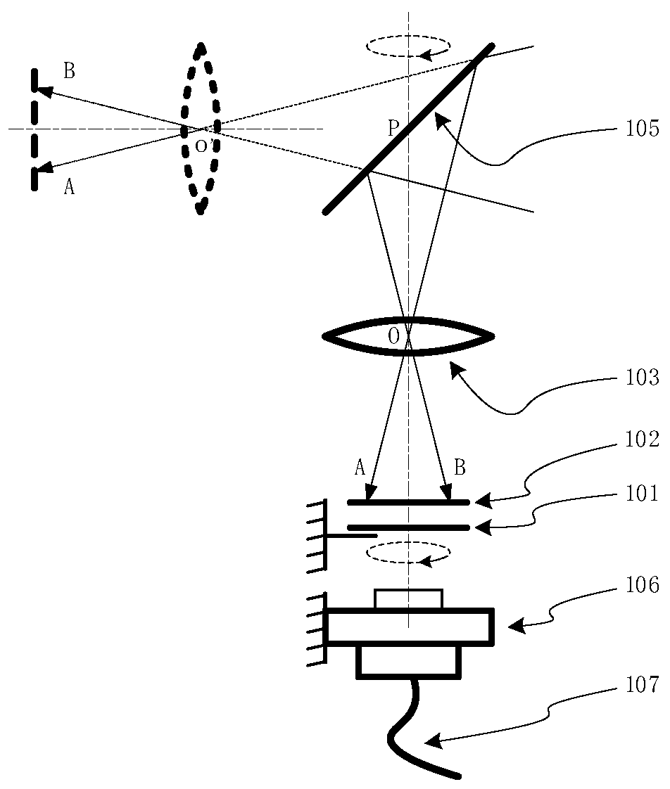
[0071] figure 2 Another schematic diagram of the structure of the video capture device provided by the embodiment of the present invention.

[0072] Such as figure 2 As shown, the video acquisition device provided by the embodiment of the present invention includes: a grating sensor 101, a line sensor 102, a lens 103, and a plane mirror 105, wherein the lens 103 is fixedly connected to the line sensor 102 and the plane mirror 105 to form a rotating body, and they rotate around the vertical axis rotation;

[0073] The line array of the line array sensor 102 passes through the longitudinal axis vertically, the optical axis of the lens 103 coincides with the longitudinal axis, and the normal line at the intersection of the plane mirror 105 and the longitudinal axis is located in the same plane as the line array;

[0074] The grating sensor 101 is configured to send sampling signals to the line sensor 102 at preset intervals,

[0075] Since the line sensor 102 and the plane m...

Embodiment 3

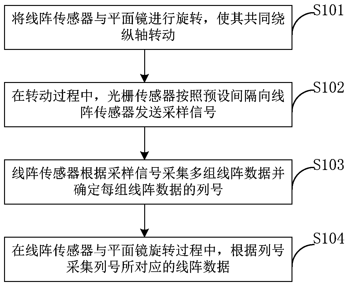
[0087] image 3 It is a flowchart of an acquisition method using a video acquisition device provided by an embodiment of the present invention.

[0088] refer to image 3 , the embodiment of the present invention provides a collection method using a video collection device. The video collection device is the video collection device of the above-mentioned embodiment, wherein the video collection device includes a line array sensor, a grating sensor, a lens, and a plane mirror. The method includes:

[0089] Step S101, rotating the line array sensor and the plane mirror so that they rotate around the longitudinal axis together;

[0090] Step S102, during the rotation process, the grating sensor sends sampling signals to the line sensor at preset intervals;

[0091] Step S103, the line array sensor collects data of multiple line arrays according to the sampling signal and determines the column number of each line array data;

[0092] Step S104, during the rotation process of th...


PUM


Abstract

The invention provides a video collection device and a collection method using the device, comprising: a line sensor, a grating sensor, a lens and a plane mirror, wherein the line sensor is fixedly connected to the plane mirror and can rotate around the longitudinal axis together, and the lens is positioned at the line sensor. Between the plane mirror and the plane mirror; the line array of the line array sensor passes through the longitudinal axis vertically, the optical axis of the lens coincides with the longitudinal axis, and the normal line at the intersection of the plane mirror and the longitudinal axis is in the same plane as the line array; the grating sensor is used for Sampling signals are sent to the line array sensors at preset intervals, and the line array sensors are used to collect multiple sets of line array data according to the sampling signals. The invention can realize video collection with wide viewing angle and high resolution.

Description

technical field [0001] The invention relates to the technical field of video collection, in particular to a video collection device and a collection method using the device. Background technique [0002] The resolution of the video system ranges from standard definition (720x576) to high definition (1920x1080), from high definition to ultra-high definition (3840x2160), continuously improving the visual experience of the audience. On the video acquisition side, this improvement in resolution mainly depends on the improvement in the resolution of the area array sensor. The photosensitive units on the area array sensor are arranged in a matrix, so it is difficult to improve the resolution. [0003] Corresponding to the area sensor, there is also a line sensor that can achieve high-resolution output. Under the premise of high resolution, in order to achieve a wide viewing angle, it can be achieved by horizontally rotating the line array sensor, but because the optical lens is ...

Claims


Application Information

Patent Timeline
IPC IPC(8): H04N7/18H04N5/232
CPCH04N7/18H04N23/60
Inventor 周骋任彦明佟欣邹箭宇张刚
Owner SUMAVISION TECH CO LTD
Learn More