Drying system of shoe-making production line

A drying system and production line technology, which is applied in the field of drying systems, can solve the problems of large power consumption and achieve the effects of energy saving, convenient operation and reduced power consumption

Inactive Publication Date: 2018-02-09
ZHAOQING CITY HI TECH ZONE XIAOJING TECH CO LTD
View PDF4 Cites 0 Cited by
  • Summary
  • Abstract
  • Description
  • Claims
  • Application Information

AI Technical Summary

Problems solved by technology

When producing shoes in large quantities, after the gluing process is completed, the shoes need to be dried rapidly and continuously. At present, shoe-making enterprises often use tunnel furnaces or drying boxes for drying. The heat sources of the above-mentioned tunnel furnaces and drying boxes are often electric heating or Infrared heating, which consumes a lot of power

Method used


Image

  • Drying system of shoe-making production line

Examples


specific Embodiment approach

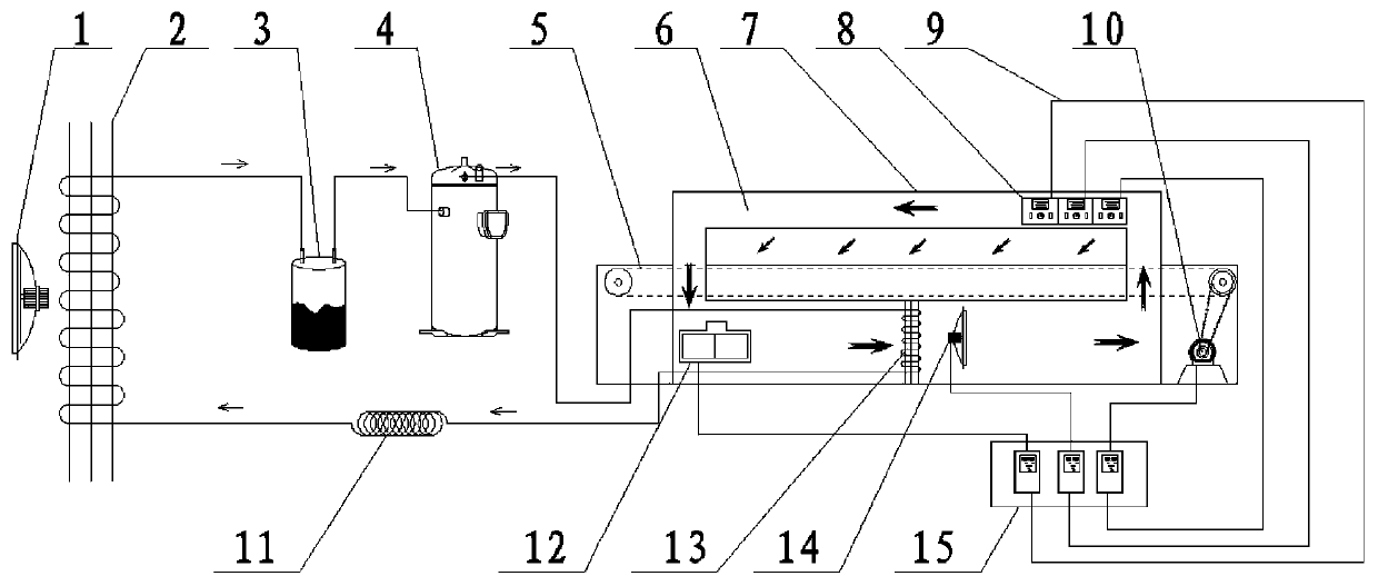
[0020] Such as figure 1 As shown, the drying system of the shoe-making production line of the present invention includes a conveyor belt 5 and a drying box 7 for conveying shoes, the conveyor belt 5 is driven by a drive motor 10, and the conveyor belt 5 passes through both sides of the drying box 7. The drying system also includes an air source heat pump device. Specifically, the evaporator 2 is sequentially connected to the gas-liquid separator 3, the compressor 4, the condenser 13, and the throttling device 11 through a refrigerant pipeline. 11 is finally connected to the evaporator 2 through the refrigerant pipe. The condenser fan 14 is installed at the end of the condenser 13, and the condenser 13 and the condenser fan 14 are installed in the drying box 7, and the condenser fan 14 allows the condenser 13 to circulate and heat the air in the drying box 7.

[0021] In order to allow the hot air to dry the shoes on the conveyor belt 5 better, the inner wall of the drying box...


PUM


Abstract

The invention provides a drying system of a shoe-making production line with low power consumption. The drying system comprises a conveyor belt used for conveying shoes and a drying box, and the conveyor belt is driven by a driving motor and penetrates through two sides of the drying box; the drying system further comprises an air source heat pump device, and the air source heat pump device is sequentially connected with an air-liquid separator, a compressor, a condenser and a throttling device through a pipe filled with a refrigeration agent; the throttling device is finally connected with anevaporator through the refrigeration agent pipe, a condenser fan is mounted at a condenser end, and the condenser and the condenser fan are mounted in the drying box. In this way, the air source heatpump device sufficiently uses the low-temperature heat energy of the evaporation end, and finally air heated by the condenser is circulated in the drying box through the condenser fan.

Description

technical field [0001] The invention relates to a drying system, which is specifically applied to drying shoes on a production line during the shoemaking process. Background technique [0002] During shoe making, the upper leather is glued to the sole with a liquid adhesive. When producing shoes in large quantities, after the gluing process is completed, the shoes need to be dried rapidly and continuously. At present, shoe-making enterprises often use tunnel furnaces or drying boxes for drying. The heat sources of the above-mentioned tunnel furnaces and drying boxes are often electric heating or Infrared heating consumes a lot of power. [0003] Heat pump technology uses a "pump" method to transmit low-temperature heat source to high-temperature end. It is a heating method that utilizes low temperature. The entire power consumption of heat pump heating is much lower than that of traditional electric heating. Contents of the invention [0004] The technical problem to be ...

Claims


Application Information

Patent Timeline
IPC IPC(8): A43D25/20
CPCA43D25/20
Inventor 张紫婷
Owner ZHAOQING CITY HI TECH ZONE XIAOJING TECH CO LTD
Why Eureka
Try Eureka