
Wind power generation unit and blade deicing system thereof

A technology for wind turbines and blades, which is applied in the field of wind turbines and blade deicing systems. It can solve problems such as the fatigue load of fan blades, the heating of three blades, and the impact on the overall service life of the fan, so as to avoid the risk of lightning damage and improve heating. Efficiency and low maintenance costs

Pending Publication Date: 2018-02-09
华润电力投资有限公司
View PDF0 Cites 11 Cited by
  • Summary
  • Abstract
  • Description
  • Claims
  • Application Information

AI Technical Summary

Problems solved by technology

[0005] However, the existing electrothermal deicing technology for fan blades has the risk of lightning strikes, the reliability of the solution is low, and expensive maintenance costs may be required later
In the existing gas-thermal deicing technology for fan blades, the power supply of the heater must pass through the hub slip ring. Because the power of the heater is relatively large, the total power of the general heating system exceeds 80 kW, or even reaches more than 200 kW, which will make the hub slip ring in the original state. The power is doubled on the basis of the design, and the cost is relatively high, especially for the technical transformation of the fan in service, it is necessary to replace a new hub slip ring, which is expensive
[0006] At the same time, in the existing gas-thermal deicing technology for fan blades, the heating device (mainly refers to the heater and blower, a complete set of about 600 kg) is installed in the impeller rotation mechanism, which has the risk of falling off and will increase the overall load of the fan, especially the fan. Blade fatigue load and pitch bearing load affect the overall service life of the fan
If the airtight space of multiple blades is heated at the same time, three heating systems are required, and the cost is high. However, if one heating system is used, the three blades cannot be heated at the same time, and dynamic deicing when the fan is running cannot be achieved.

Method used


Image

  • Wind power generation unit and blade deicing system thereof
  • Wind power generation unit and blade deicing system thereof

Examples


Embodiment Construction

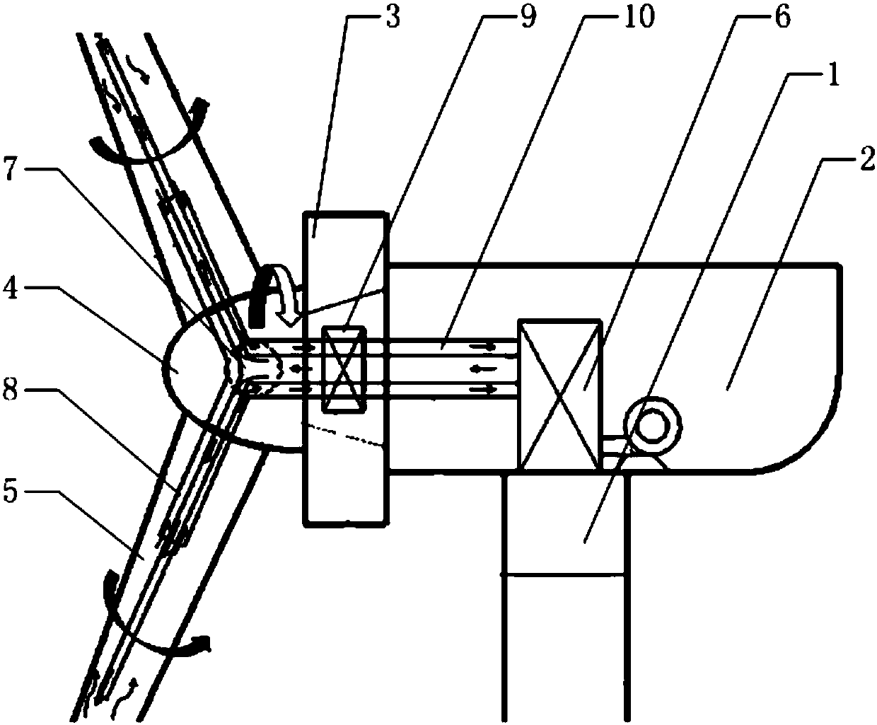
[0023] The core of the present invention is to provide a blade deicing system of a wind power generating set, which is efficient, fast and low in cost. Another core of the present invention is to provide a wind power generating set including the above-mentioned blade deicing system, which has high efficiency, quick deicing and low cost.

[0024] In order to enable those skilled in the art to better understand the solution of the present invention, the present invention will be further described in detail below in conjunction with the accompanying drawings and specific embodiments.

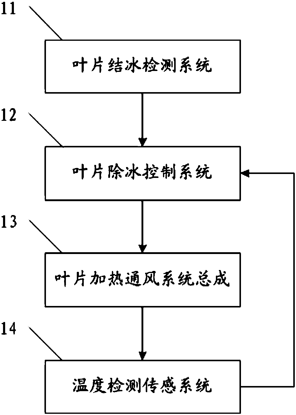
[0025] Please refer to figure 1 , figure 1 It is a structural schematic diagram of a specific embodiment of the wind power generating set provided by the present invention; figure 2 It is a functional block diagram of a specific implementation manner of the blade deicing system of the wind power generating set provided by the present invention.

[0026] The specific embodiment of the present in...


PUM


Abstract

The invention discloses a blade deicing system of a wind power generation unit. The blade deicing system comprises an air heating and outputting device arranged at the top end of a tower drum of the wind power generation unit, a multi-through connector arranged in a hub of the wind power generation unit and blade ventilation pipelines arranged in corresponding blades of the wind power generation unit; an air outlet of the air heating and outputting device communicates with one port of the multi-through connector through a rotary connector; and the other joints of the multi-through connector communicate with tail ends of the corresponding blade ventilation pipelines. By adopting the blade deicing system provided by the invention, the risk of mounting dropping is avoided, fatigue load of a relative component of a fan is reduced, the reliability is improved, and the service life of the component is prolonged; without arranging a hub sliding ring, the cost is remarkably lowered; the heating efficiency is improved, and in addition, as the fan can work both when stopping and running, the cost is low; and the risk of damage by lightning is avoided, the reliability is high, and the maintenance cost is low. The invention also discloses the wind power generation unit comprising the blade deicing system.

Description

technical field [0001] The invention relates to the field of wind power generation, in particular to a blade deicing system of a wind power generating set. In addition, the present invention also relates to a wind power generating set comprising the above-mentioned blade deicing system. Background technique [0002] With the gradual depletion of global fossil energy and the deterioration of climate problems, wind power as a clean energy is expected to improve this situation. With the advancement of technology, wind power has gradually become prominent in the proportion of energy structure. Wind power generation operates in cold weather conditions, and the blades of the fan are prone to ice formation, which will damage the original aerodynamic characteristics of the blades, reduce the power output, and be forced to shut down in serious cases, thereby reducing the power generation of the unit. When the blades freeze, it will increase the additional load of the unit, and long-...

Claims


Application Information

Patent Timeline
Patent Type & Authority Applications(China)
IPC IPC(8): F03D80/40F03D80/60F03D1/06F03D9/25
CPCF03D1/0675F03D1/0691F03D9/25F03D80/40F03D80/60Y02E10/72
Inventor 田鹏辉王进苏小溪
Owner 华润电力投资有限公司
Learn More