Electric push rod

An electric push rod, motor-driven technology, applied in the direction of electric components, electrical components, electromechanical devices, etc., can solve the problems of increasing the vibration and noise of worm gears and affecting the meshing quality of worm gears, and achieves noise reduction, meshing quality improvement, and transmission. The effect of improving efficiency

Pending Publication Date: 2018-02-09
ZHEJIANG JIECHANG LINEAR MOTION TECH
View PDF0 Cites 8 Cited by
  • Summary
  • Abstract
  • Description
  • Claims
  • Application Information

AI Technical Summary

Problems solved by technology

[0002] Electric push rods, generally also called linear actuators, its main working principle is to drive the screw rod to rotate through the motor, and the drive nut is set on the screw rod. When the screw rod rotates, it drives the drive nut to reciprocate, and the motor and the screw rod are usually used The worm gear mechanism is used to realize the transmission. In the existing electric push rod, the transmission worm is generally integrated with the output shaft of the motor to facilitate assembly. However, this structure also has certain disadvantages. The vibration of the output shaft of the motor will be directly transmitted to the transmission worm On the surface, it will affect the meshing quality of the worm gear to a certain extent, and it will also increase the vibration and noise between the worm gear and worm

Method used


Image

  • Electric push rod
  • Electric push rod
  • Electric push rod

Examples


Embodiment 1

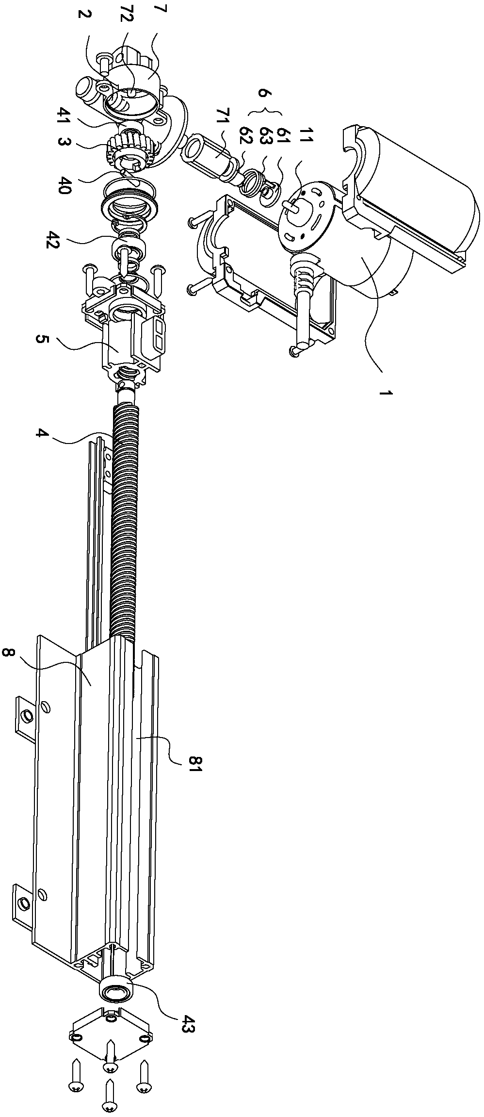
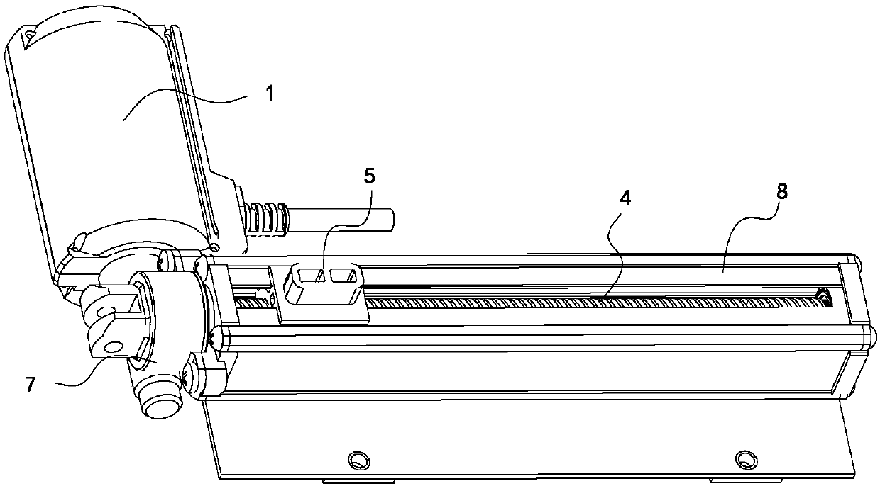
[0030] Such as Figure 1 to Figure 7 As shown, an electric push rod shown in this embodiment includes a motor 1, a transmission worm 2, a transmission worm wheel 3, a screw 4 and a transmission nut 5, the rotation of the motor 1 drives the transmission worm 2 to rotate, and the transmission worm 2 is connected with the transmission When the worm gear 3 is meshed, the rotation of the transmission worm 2 drives the transmission worm 3 to rotate, and the rotation of the transmission worm 3 drives the screw 4 to rotate. The screw 4 is connected to the transmission nut 5. When the screw 4 itself rotates, the transmission nut 5 moves The axial direction of the screw rod 4 moves relatively, thereby converting the rotational motion of the motor 1 into the linear reciprocating motion of the transmission nut 5, and the transmission nut 5 can be used to connect other components to push related components to move, such as lifting tables, medical bed etc.

[0031] In the present invention...

Embodiment 2

[0054] The difference between this embodiment and Embodiment 1 is that the connection structure between the transmission worm wheel and the screw rod is connected by a spline, that is, a spline groove is provided on the transmission worm wheel, and the end of the screw rod is provided with a The splines matched with the spline grooves can be axially inserted into the spline grooves to realize the transmission of the two.


PUM


Abstract

The invention discloses an electric push rod, belonging to the technical field of linear transmission, comprising a motor, a transmission worm, a transmission worm wheel, a screw and a transmission nut, the motor drives the transmission worm to rotate, the transmission worm drives the screw to rotate, and the connection between the transmission worm and the transmission worm Intermeshing transmission, the motor includes an output shaft, the output shaft and the transmission worm are separately arranged, and the output shaft and the transmission worm are connected through a backstop. The invention has the advantages of reducing the vibration and transmission noise at the transmission worm, and at the same time improving the self-locking ability of the electric push rod when it moves in the reverse direction.

Description

【Technical field】 [0001] The invention relates to an electric push rod, which belongs to the technical field of linear transmission. 【Background technique】 [0002] Electric push rods, generally also called linear actuators, its main working principle is to drive the screw rod to rotate through the motor, and the drive nut is set on the screw rod. When the screw rod rotates, it drives the drive nut to reciprocate, and the motor and the screw rod are usually used The worm gear mechanism is used to realize the transmission. In the existing electric push rod, the transmission worm is generally integrated with the output shaft of the motor to facilitate assembly. However, this structure also has certain disadvantages. The vibration of the output shaft of the motor will be directly transmitted to the transmission worm In fact, it will affect the meshing quality of the worm gear to a certain extent, and it will also increase the vibration and noise between the worm gear and worm. ...

Claims


Application Information

Patent Timeline
Patent Type & Authority Applications(China)
IPC IPC(8): F16H37/12H02K7/06
CPCF16H37/124H02K7/06
Inventor 陆小健翟鑫马勇
Owner ZHEJIANG JIECHANG LINEAR MOTION TECH
Why Eureka
Try Eureka