Supercharge Your Innovation With Domain-Expert AI Agents!

Display panel

A display panel and display area technology, applied in the direction of photographic process, optics, instruments, etc. on the pattern surface, can solve the problems of difficult monitoring and the inability to determine the effective boundary of the color resistance of the last color, etc.

Active Publication Date: 2018-02-09
HKC CORP LTD
View PDF6 Cites 4 Cited by
  • Summary
  • Abstract
  • Description
  • Claims
  • Application Information

AI Technical Summary

Problems solved by technology

[0003] As the resolution of the display device becomes higher and higher, the aperture ratio of the corresponding pixels becomes smaller and smaller, and the width of the black matrix becomes smaller and smaller. This trend affects the critical dimension (CD) of each color resistance on the display device. The monitoring of the
When the color resistance of the first color is completed, there is no problem in the corresponding CD measurement, but after the color resistance of the last color is completed, due to the process capability, the color resistance of different colors has overlapped, or the distance It is too close, so it is impossible to determine the effective boundary of the color resistance of the last color by means of grayscale measurement and other means, and it is also impossible to perform CD measurement on it

Method used


Image

  • Display panel
  • Display panel
  • Display panel

Examples


Embodiment Construction

[0026] The following descriptions of the various embodiments refer to the accompanying drawings to illustrate specific embodiments in which the present invention can be practiced. The directional terms mentioned in the present invention, such as "up", "down", "front", "back", "left", "right", "inside", "outside", "side", etc., are for reference only The orientation of the attached schema. Therefore, the directional terms used are used to illustrate and understand the present invention, but not to limit the present invention.

[0027] The drawings and descriptions are to be regarded as illustrative in nature and not restrictive. In the figures, structurally similar units are denoted by the same reference numerals. In addition, the size and thickness of each component shown in the drawings are arbitrarily shown for understanding and ease of description, but the present invention is not limited thereto.

[0028] In the drawings, the thickness of layers, films, panels, regions,...


PUM


Abstract

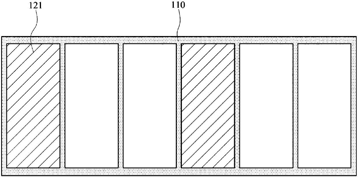
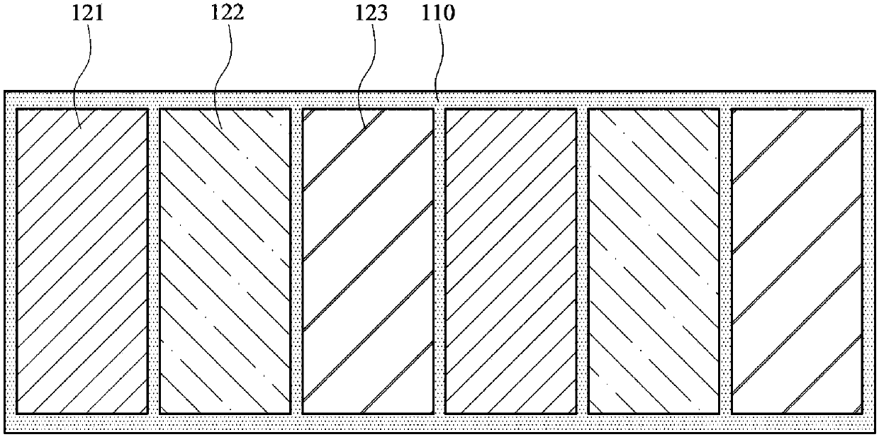
The embodiment of the invention provides a display panel. The display panel comprises a first substrate, a second substrate, a light shield layer, a color resistance layer and multiple automatic switches, wherein the first substrate is arranged opposite to the second substrate, and the first substrate comprises a display area and a wiring area; the light shield layer is arranged in the display area of the first substrate and on the periphery of the display area, and the display area and the wiring area are defined by the light shield layer; the color resistance layer includes a first color resistance layer and a second color resistance layer, wherein the first color resistance layer is arranged in the display area of the first substrate in an arrayed mode and located between the light shield layer, the second color resistance layer is arranged in the wiring area of the first substrate in an arrayed mode and surrounds the light shield layer, the second color resistance layer comprises auxiliary color resistors and marked color resistors clamped between the auxiliary color resistors, and the marked color resistors are provided with marked structures; the multiple automatic switches are arranged on either the first substrate or the second substrate; the auxiliary color resistors and the marked color resistors adjacently arranged at intervals are arranged on at least one side of the first substrate. According to the display panel, the marked structures are designed on the color resistance layer of the wiring area of the display panel, so that the display panel is not influencedby goodness of the manufacture procedure, and the critical dimension of the color resistors is better measured.

Description

technical field [0001] The invention relates to the display field, in particular to a display panel with marked color resistance in the wiring area. Background technique [0002] With the development of flat panel display technology, liquid crystal display (Liquid-crystal Display; LCD) has gradually replaced traditional anode ray tube display devices due to its superior characteristics such as light and thin body, low power consumption and no radiation. A liquid crystal display device includes a backlight module and a display panel. A display panel usually consists of a color filter substrate (Color Filter, CF), a thin film transistor array substrate (Thin Film Transistor Array Substrate, TFT Array Substrate), and a liquid crystal layer (Liquid Crystal Layer, LC Layer) arranged between the two substrates. Its working principle is to control the rotation of the liquid crystal molecules in the liquid crystal layer by applying a driving voltage on the two glass substrates, and...

Claims


Application Information

Patent Timeline
IPC IPC(8): G02F1/1335G03F1/38
CPCG02F1/133514G03F1/38
Inventor 黄北洲
Owner HKC CORP LTD
Features
  • R&D
  • Intellectual Property
  • Life Sciences
  • Materials
  • Tech Scout
  • Unparalleled Data Quality
  • Higher Quality Content
  • 60% Fewer Hallucinations
Learn More