Solid-state relay

A solid-state relay and circuit technology, applied in instruments, simulators, electrical components, etc., can solve problems such as reducing system reliability, increasing system complexity, and inability to interchange power supply and load terminals, and achieve the effect of extending service life.

Pending Publication Date: 2018-02-09
北京国科天宏自动化技术有限公司
View PDF0 Cites 2 Cited by
  • Summary
  • Abstract
  • Description
  • Claims
  • Application Information

AI Technical Summary

Problems solved by technology

[0003] It can be seen that the existing solid-state relays can only rely on the externally provided control power to maintain the on-off state, and the control power must always exist, which reduces the reliability of the system, and

Method used


Image

  • Solid-state relay
  • Solid-state relay
  • Solid-state relay

Examples


Embodiment Construction

[0027] The principles and features of the present invention are described below in conjunction with the accompanying drawings, and the examples given are only used to explain the present invention, and are not intended to limit the scope of the present invention.

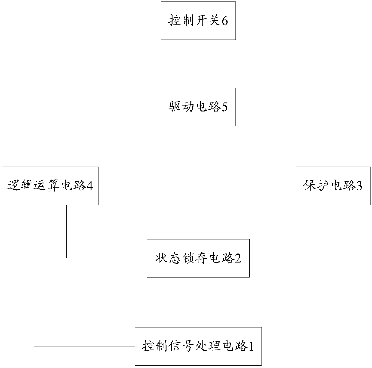
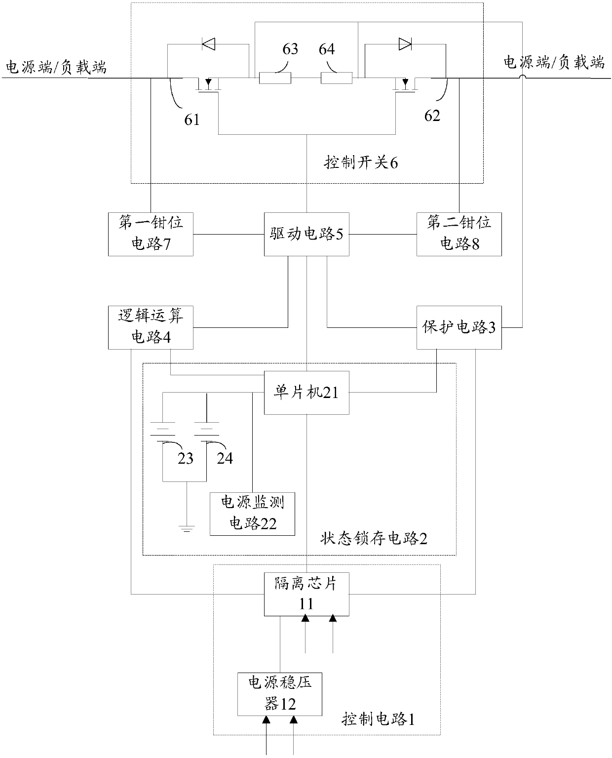
[0028] Such as figure 1 As shown, it is a schematic structural diagram of a solid-state relay provided by Embodiment 1 of the present invention. The solid-state relay includes: a control signal processing circuit 1, a state latch circuit 2, a protection circuit 3, a logic operation circuit 4, a drive circuit 5 and a control circuit switch 6, wherein the state latch circuit 2 is respectively connected to the control signal processing circuit 1, the protection circuit 3, the logic operation circuit 4 and the drive circuit 5, the control signal processing circuit 1 is also connected to the logic operation circuit 4, and the logic operation circuit 4 is also connected It is connected with the driving circuit 5, and the...


PUM


Abstract

The invention relates to a solid-state relay, comprising: a control signal processing circuit, a state latch circuit, a protection circuit, a logical operation circuit, a drive circuit and a control switch, wherein the state latch circuit is connected with the control signal processing circuit, the protection circuit, the logic The operation circuit is connected with the drive circuit, the control signal processing circuit is also connected with the logic operation circuit, the logic operation circuit is also connected with the drive circuit, and the drive circuit is also connected with the control switch. A solid-state relay provided by the present invention realizes that even if the external control power supply input is cut off, the control switch can be kept in the previous on or off state. Extremely low, which is beneficial to prolong the service life of solid state relays with state holding function.

Description

technical field [0001] The invention relates to the field of relays, in particular to a solid-state relay with a state holding function. Background technique [0002] At present, solid-state relays can be divided into semi-controlled solid-state relays and full-control solid-state relays according to the controllability of semiconductor devices. Take the fully controlled solid state relay as an example, such as image 3 As shown, the switching devices are mainly MOSFET (Metal-Oxide-Semiconductor Field-Effect Transistor, Metal-Oxide Semiconductor Field-Effect Transistor) and IGBT (Insulated Gate Bipolar Transistor, insulated gate bipolar transistor), which are composed of two common sources MOSFETs and IGBTs with two poles form a bidirectional controllable switch 37. During normal operation, control power is provided to the interface circuit 31, and the interface circuit 31 isolates the power and sends it to the controller 32 and other internal detection circuits, including ...

Claims


Application Information

Patent Timeline
IPC IPC(8): H03K17/081H03K17/567G05B19/042
CPCH03K17/08116H03K17/567G05B19/0423
Inventor 刘武超张保冰
Owner 北京国科天宏自动化技术有限公司
Why Eureka
Try Eureka