AI technical title is built by PatSnap AI team. It summarizes the technical point description of the patent document.
A technology for converting circuits and levels
Active Publication Date: 2018-02-09
YANGTZE MEMORY TECH CO LTD
View PDF6 Cites 0 Cited by
Summary
Abstract
Description
Claims
Application Information
AI Technical Summary
This helps you quickly interpret patents by identifying the three key elements:
Problems solved by technology
Method used
Benefits of technology
Problems solved by technology
In the above discharge process, it takes a long time to turn off the switch tube K3, and the power supply hv_sup continues to charge the node g_hv, resulting in a large power consumption during the discharge process and increasing the power consumption of the system
Method used
Image
Click on the blue label to locate the original text in one second.
Reading with bidirectional positioning of images and text.
Examples
Embodiment 1
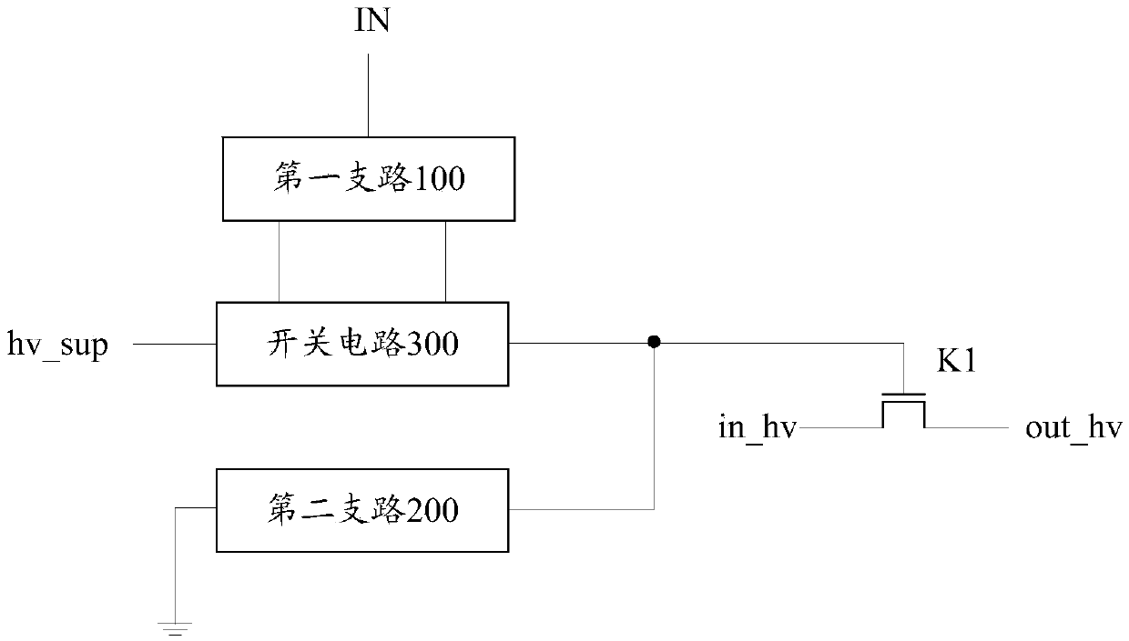
[0062] see figure 2 , which is a schematic structural diagram of a level conversion circuit provided in an embodiment of the present application.
[0063] The level conversion circuit provided in the embodiment of the present application includes: a first branch circuit 100, a second branch circuit 200, a switch circuit 300 and a first switch tube K1;
[0064] The input terminal of the first branch 100 is the input terminal IN of the level conversion circuit, the first output terminal of the first branch 100 is connected to the first control terminal of the switch circuit 300, and the second output terminal of the first branch 100 is connected to the switch A second control terminal of the circuit 300;
[0065] The first end of the switch circuit 300 is connected to the first auxiliary power supply hv_sup, the second end of the switch circuit 300 is connected to the first end of the second branch 200, and the second end of the second branch 200 is grounded;
[0066] The con...
Embodiment 2
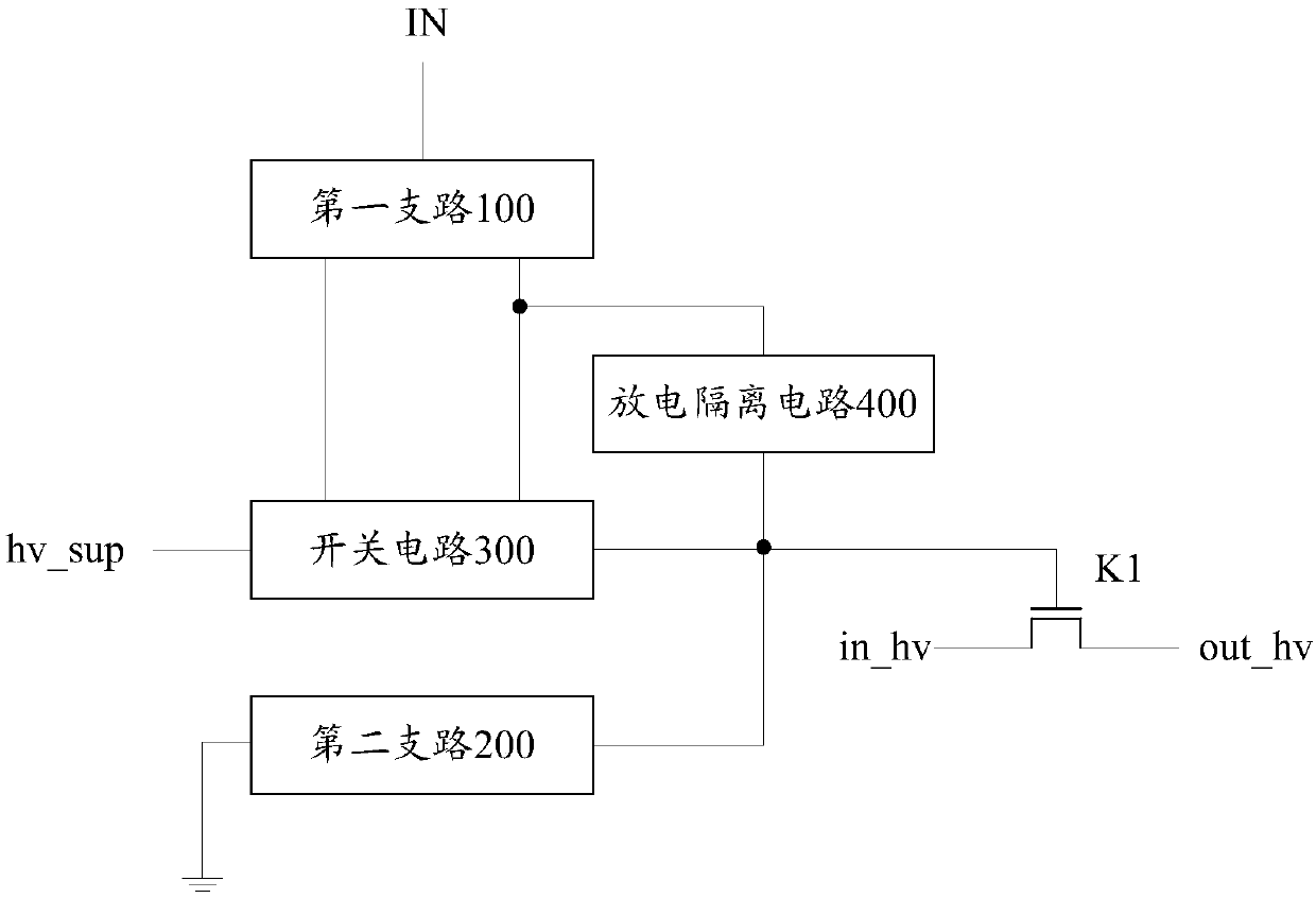
[0072] see image 3 , which is a schematic structural diagram of another level conversion circuit provided in the embodiment of the present application. Compared to figure 2 , this figure provides a more concrete level shifting circuit.
[0073] In the embodiment of the present application, the level conversion circuit may further include: a discharge isolation circuit 400;
[0074] A first end of the discharge isolation circuit 400 is connected to the first output end of the first branch 100 , and a second end of the discharge isolation circuit 400 is connected to the first end of the second branch 200 .
[0075] When the input terminal IN of the level conversion circuit turns to a low level, the discharge isolation circuit 400 can isolate the switch circuit 300 and the control terminal of the first switch tube K1 to discharge through the first branch 100 and the second branch 200 respectively; When the input terminal IN of the level conversion circuit inputs a high level...
Embodiment 3
[0086] see Figure 5 , which is a circuit topology diagram of a level conversion circuit provided in a specific embodiment of the present application. Compared to figure 2 and image 3 , this figure provides a more concrete level shifting circuit.
[0087] Figure 5 The circuit topology of the level conversion circuit provided by the specific embodiment of the present application is shown only by taking the discharge isolation circuit including an isolation resistor R as an example. The two ends of the isolation resistor R are respectively connected to the first output end of the first branch and the second branch. The second end of the circuit, other implementations of the discharge isolation circuit will not be listed here.
[0088] In the embodiment of the present application, the first branch may specifically include: a first inverter Inv1 and a second inverter Inv2;
[0089] The input end of the first inverter Inv1 is the input end of the first branch, and the outpu...
PUM
Abstract
The embodiments of application disclose a level converting circuit. The level converting circuit includes a first branch, a second branch, a switch circuit and a first switch tube. An input end of thefirst branch is an input end of the level converting circuit. A first output end and a second output end are in separate connection to a first control end a second control end of the switch circuit.A first end of the switch circuit is connected to a first auxiliary power supply, a second end is connected to a first end of the second branch, and a second end of the second branch is grounded. A control end of the first switch tube is connected to a second end of the switch circuit, a first end of the first switch tube is connected to a second auxiliary power supply, and a second end of the first switch tube is an output end of the level converting circuit. In the discharging process, the switch circuit performs charging through the first branch, the switch circuit is quickly disconnected,the control end of the first switch tube performs discharging through the second branch, such that the switching-off of the first switch tube is shortened, the output of the level converting circuit can be quickly converted from high level to low level, the power loss of the level converting circuit is reduced, and the systempower loss is also reduced.
Description
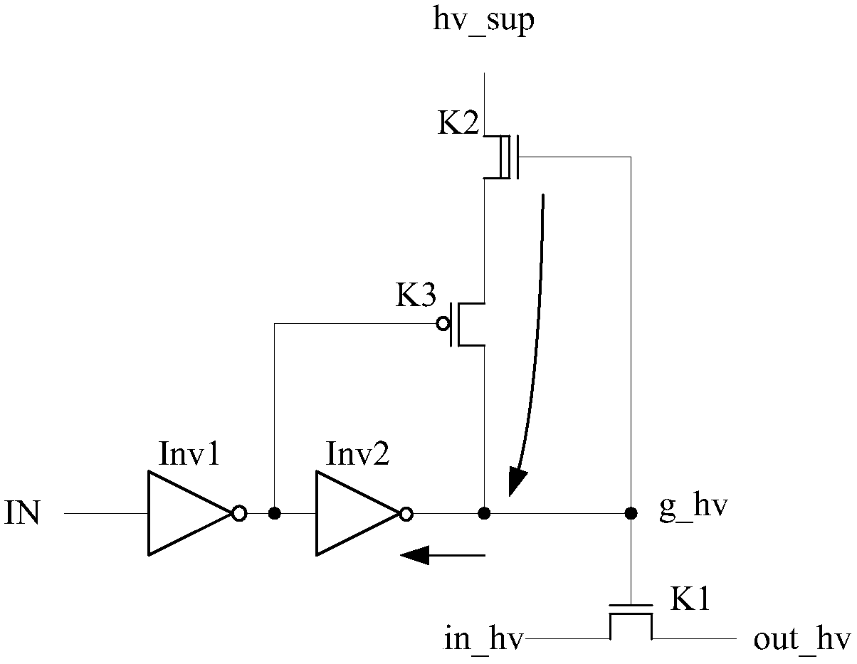
technical field [0001] The present application relates to the technical field of power electronics, in particular to a level conversion circuit. Background technique [0002] In the design of electronic circuits, the logic inconsistency between input and output often occurs inside the system, which increases the complexity of system design. For example, when a 1.8V digital circuit communicates with an analog circuit operating at 3.3V, it is necessary to first solve the conversion problem of the two levels. At this time, a level conversion circuit is required to enable the two circuits to communicate normally. [0003] figure 1 A conventional level shifting circuit is shown. During the discharge process from high level to low level conversion, the third switch tube K3 figure 1 The path indicated by the middle arrow is discharged until the voltage at the node g_hv drops to the point where the switch tube K1 is turned off, and the level conversion circuit outputs a low level...
Claims
Application Information
Patent Timeline
Application Date:The date an application was filed.
Publication Date:The date a patent or application was officially published.
First Publication Date:The earliest publication date of a patent with the same application number.
Issue Date:Publication date of the patent grant document.
PCT Entry Date:The Entry date of PCT National Phase.
Estimated Expiry Date:The statutory expiry date of a patent right according to the Patent Law, and it is the longest term of protection that the patent right can achieve without the termination of the patent right due to other reasons(Term extension factor has been taken into account ).
Invalid Date:Actual expiry date is based on effective date or publication date of legal transaction data of invalid patent.

