Clothes dryer and control method
A technology for clothes dryers and clothes, which is applied in the field of clothes dryers, and can solve the problems of low drying rate of clothes dryers, slow temperature raising speed of clothes dryers, and high energy consumption at start-up, so as to avoid scald accidents and speed up clothes drying speed , Reduce the effect of starting energy consumption
- Summary
- Abstract
- Description
- Claims
- Application Information
AI Technical Summary
Problems solved by technology
Method used
Image
Examples
Embodiment 1
[0042] In this embodiment, the steam generator 8 of the clothes dryer can be any existing steam generator with the following structure: a body forming a chamber with a certain volume is provided, and a chamber for converting water into steam is provided in the chamber. The heating device is provided with a water inlet for water to enter the chamber and an air outlet for steam to flow out of the chamber on the body.
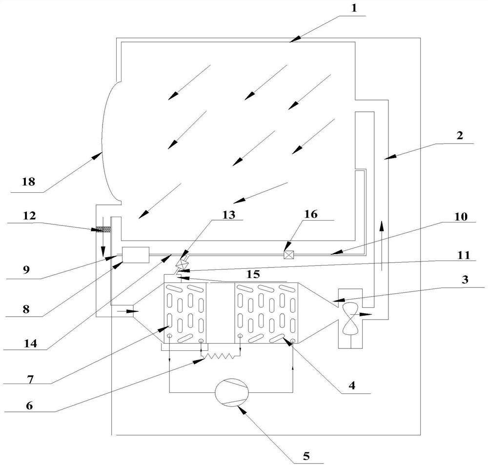
[0043] like figure 1 As shown, in this embodiment, the gas outlet of the steam generator 8 communicates with one end of the first pipeline 14, and the other end of the first pipeline 14 communicates with the first branch pipe 10 and the second branch pipe 11 respectively, and the first branch pipe 10 communicates with the outer cylinder 1 , and the second branch pipe 11 communicates with the shower 15 .
[0044] In this embodiment, the first branch pipe 10 and the second branch pipe 11 are respectively provided with a first valve 16 and a second valve 13 for cont...
Embodiment 2
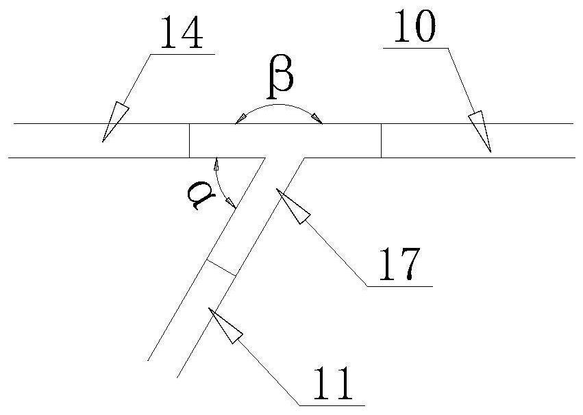
[0050] The difference between this embodiment and the first embodiment above is that: figure 1 As shown, the axial angle between the first branch pipe 10 and the first pipe 14 is greater than the axial angle between the second branch pipe 11 and the first pipe 14 . Through the above settings, the tee structure at the intersection of the first branch pipe 10, the second branch pipe 11 and the first pipe 14 has a Venturi effect, so that most of the steam in the first pipe 14 flows to the first branch pipe 10, and a small part flows to the second branch pipe 14. branch pipe 11.
[0051] like figure 2 As shown, in this embodiment, one end of the first pipe 14 communicates with the gas outlet of the steam generator 8 , and the other end communicates with the first branch pipe 10 and the second branch pipe 11 through the tee 17 . Described tee 17 comprises air inlet section, first air outlet section and second air outlet section, and one end of inlet section, first air outlet sec...
Embodiment 3
[0057] The difference between this embodiment and the first to second embodiments above is that the first branch pipe 10 is inclined upward or parallel to the horizontal plane; the second branch pipe 11 is inclined downward relative to the horizontal plane. Under the above conditions, the ungasified water produced by the steam generator 8 automatically flows into the shower 15 arranged above the evaporator 7 under the action of gravity to spray the evaporator 7 to remove the lint attached to the evaporator 7 , and sterilize the evaporator 7 and its surrounding components.
[0058] In this embodiment, the corresponding states during the working process of the clothes dryer are as follows:
[0059] State 1. During normal steam treatment of clothes, when the door 18 at the clothes inlet of the clothes dryer is closed, the first valve 16 and the second valve 13 are opened at the same time, and the air outlet of the steam generator 8 is connected to the outer cylinder. 1 and the s...
PUM
 Abstract
Description
Claims
Application Information
 - R&D
- Intellectual Property
- Life Sciences
- Materials
- Tech Scout
- Unparalleled Data Quality
- Higher Quality Content
- 60% Fewer Hallucinations
Browse by: Latest US Patents, China's latest patents, Technical Efficacy Thesaurus, Application Domain, Technology Topic, Popular Technical Reports.
© 2025 PatSnap. All rights reserved.Legal|Privacy policy|Modern Slavery Act Transparency Statement|Sitemap|About US| Contact US: help@patsnap.com


