Drying box for sealing piece production

A drying box and sealing technology, applied in progressive dryer, drying gas arrangement, drying and other directions, can solve the problems of complex internal structure of drying device, incomplete drying of drying device, affecting the performance of seals, etc. Drying speed, fast speed, and the effect of meeting production needs

Pending Publication Date: 2018-02-13
盐城润浩密封件科技有限公司
14 Cites 2 Cited by

AI-Extracted Technical Summary

Problems solved by technology

[0003] 1. The internal structure of the drying device is complex and the operation is cumbersome, so it is not suitable for beginners
[0004] 2. The drying devi...

Abstract

The invention discloses a drying box for sealing piece production. The drying box comprises an air distribution disc, a drying box body and a conveyor belt. The air distribution disc is fixed to the center of the drying box body, and the upper end of the air distribution disc communicates with an air blower; the air blower is fixed to the upper end of the drying box body through a fixing support,and the center of the air distribution disc is provided with a ventilating pipe; an iron wire net is welded to the center of the drying box body, and heating wires are laid in the center of the iron wire net; and the conveyor belt is arranged below the iron wire net, and a rotary roller is sleeved with the inner surface wall of the conveyor belt. According to the drying box for sealing piece production, a sealing piece is dried through air flowing, the multi-hole conveyor belt is arranged on the device, the contact area of the sealing piece and the conveyor belt is decreased, water leakage canbe achieved, and the drying speed of the sealing piece can further be increased; and movement of water molecules on the surface of the sealing piece is accelerated through an high-temperature air flow, and through a low-temperature drying pipe, drying is more thorough.

Application Domain

Technology Topic

Image

  • Drying box for sealing piece production
  • Drying box for sealing piece production
  • Drying box for sealing piece production

Examples

  • Experimental program(1)

Example Embodiment

[0018] The technical solutions in the embodiments of the present invention will be clearly and completely described below in conjunction with the accompanying drawings in the embodiments of the present invention. Obviously, the described embodiments are only a part of the embodiments of the present invention, rather than all the embodiments. Based on the embodiments of the present invention, all other embodiments obtained by those of ordinary skill in the art without creative work shall fall within the protection scope of the present invention.
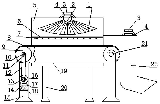
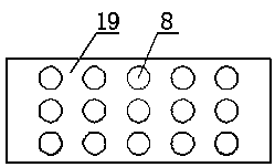
[0019] See Figure 1-3 , The present invention provides a technical solution: a drying box for the production of seals, comprising an air distribution plate 2, a drying box 5 and a conveyor belt 19, the air distribution plate 2 is fixed at the center of the drying box 5, the air distribution The upper end of the disk 2 communicates with a blower 3, the blower 3 is fixed to the upper end of the drying box 5 by a fixing bracket 4, a ventilation pipe 1 is opened at the center of the air distribution plate 2, and the center of the drying box 5 is welded A wire mesh 6, a heating wire 7 is laid at the center of the wire mesh 6, and a conveyor belt 19 is arranged below the wire mesh 6, and the inner surface of the conveyor belt 19 is covered with a roller 9, and the roller 9 is provided with two , And two rotating rollers 9 are distributed at both ends of the inner surface wall of the conveyor belt 19, and a rotating shaft 10 is fixed at the center of the rotating roller 9, and a driven wheel 11 is welded on the outer surface wall on one side of the rotating shaft 10, the driven wheel 11 The drive wheel 13 is connected by a belt 12, the drive wheel 13 is fixed on the outer wall of the power shaft 16, the other side of the power shaft 16 is connected to a motor 17, and the motor 17 is fixed to the cross bar by a fixed base 14 18 above, the cross bar 18 is fixedly embedded in the middle of the two support rods 15, the upper end of the support rod 15 is inlaid with a bearing 21, the center of the bearing 21 is movably sleeved with a rotating shaft 10, the drying box 5 A drying tube 22 is provided on one side, and the upper end of the drying tube 22 communicates with the blower 3.
[0020] The lower end of the drying box 5 is welded with a box support rod 20. The box support rod 20 and the lower wall of the support rod 15 are on the same level. A circular hole 8 is opened above the conveyor belt 19, which can not only leak water but also Airflow drying provides conditions. Both the blower 3 and the heating wire 7 are electrically connected to an external power source. A slot 23 is provided at the junction of the conveyor belt 19 and the drying box 5 to provide space for the conveyor belt 19 to be used normally.
[0021] Working principle: When the drying box for the production of the seal is used, the motor 17 and the blower 3 are electrically connected with the external power source, the power shaft 16 rotates, and the belt 12 transmits the rotating shaft 10 to rotate, thereby driving The roller 9 rotates, and finally the conveyor belt 19 moves. The operator puts the seal on the moving conveyor belt 19. After the seal reaches the drying box 5, the wind generated by the blower 3 is blown out evenly by the ventilation pipe 1 in the air distribution plate 2 , The heat generated by the heating wire 7 is evenly blown to the sealing member, and the water stains on the surface of the sealing member are dried by the airflow of higher temperature. With the movement of the conveyor belt 19, it falls into the drying tube 22. During the falling process, The upper blower 3 continuously blows air with a lower temperature into the drying tube 22, and then dries the seals again and thoroughly.
[0022] Although the embodiments of the present invention have been shown and described, those of ordinary skill in the art can understand that various changes, modifications, and substitutions can be made to these embodiments without departing from the principle and spirit of the present invention. And variations, the scope of the present invention is defined by the appended claims and their equivalents.

PUM

no PUM

Description & Claims & Application Information

We can also present the details of the Description, Claims and Application information to help users get a comprehensive understanding of the technical details of the patent, such as background art, summary of invention, brief description of drawings, description of embodiments, and other original content. On the other hand, users can also determine the specific scope of protection of the technology through the list of claims; as well as understand the changes in the life cycle of the technology with the presentation of the patent timeline. Login to view more.

Similar technology patents

Ablation catheter with grooves in surface

ActiveCN103505798AReduce contact areaReduce frictional resistanceCatheterSurgical ManipulationGuiding catheter
Owner:SHANGHAI GOLDEN LEAF MED TEC

Phase change memory element and manufacturing method thereof

ActiveCN102386323AImprove read and write speedReduce contact areaElectrical apparatusNanometreOptoelectronics
Owner:SEMICON MFG INT (SHANGHAI) CORP +1

Classification and recommendation of technical efficacy words

  • Reduce contact area
  • Fast drying
Why Eureka
Try Eureka