Micro loop heat pipe and method

A loop heat pipe and micro technology, applied in the field of heat pipes, can solve problems such as affecting the heat transfer performance of the micro loop heat pipe, and achieve the effect of strengthening heat transfer

Pending Publication Date: 2018-02-13
SOUTH CHINA UNIV OF TECH
View PDF11 Cites 2 Cited by
  • Summary
  • Abstract
  • Description
  • Claims
  • Application Information

AI Technical Summary

Problems solved by technology

[0008] The purpose of the present invention is to overcome the shortcomings and deficiencies of the above-mentioned prior art, provide a simple structure, high heat transfer efficiency micro loop heat pipe and method, solve the problem of affecting the heat transfer performance of the micro loop heat pipe due to the agglomeration of nano fluids

Method used


Image

  • Micro loop heat pipe and method
  • Micro loop heat pipe and method

Examples


Embodiment

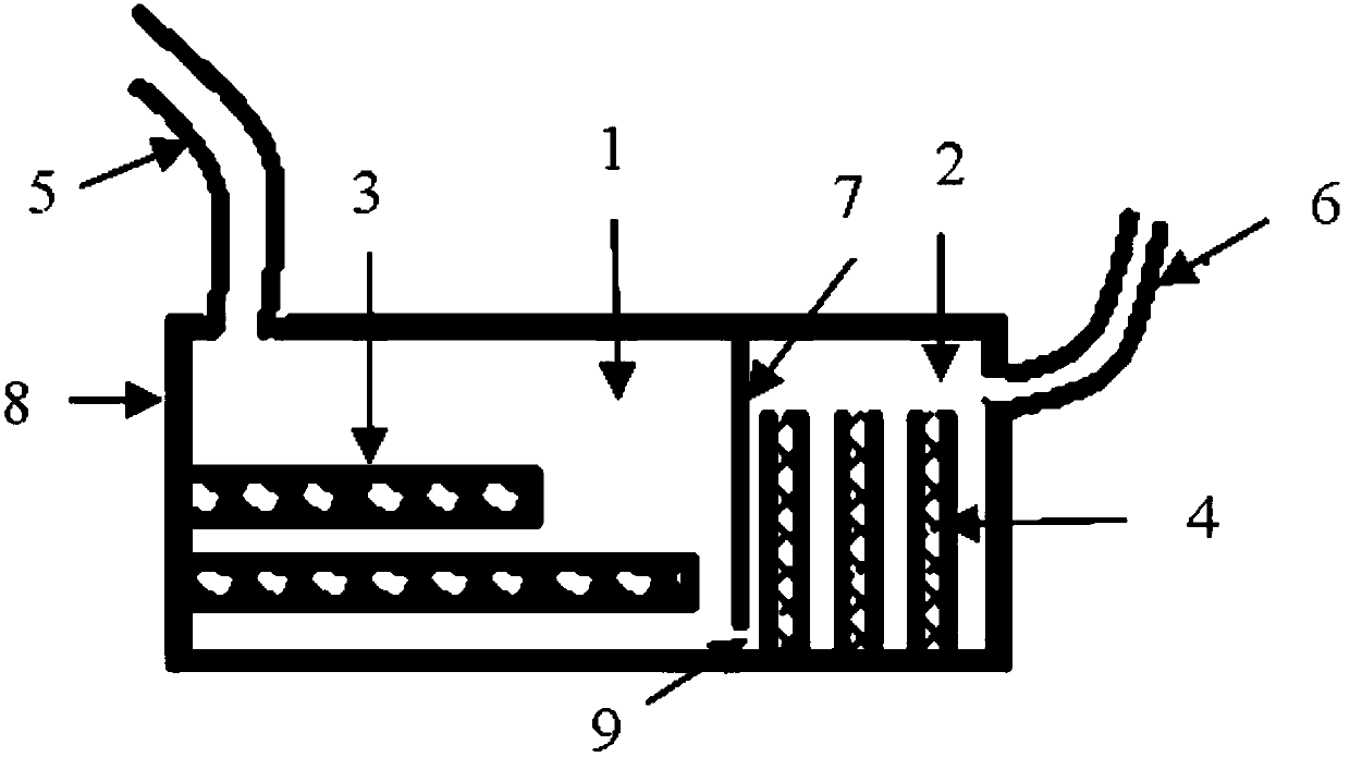
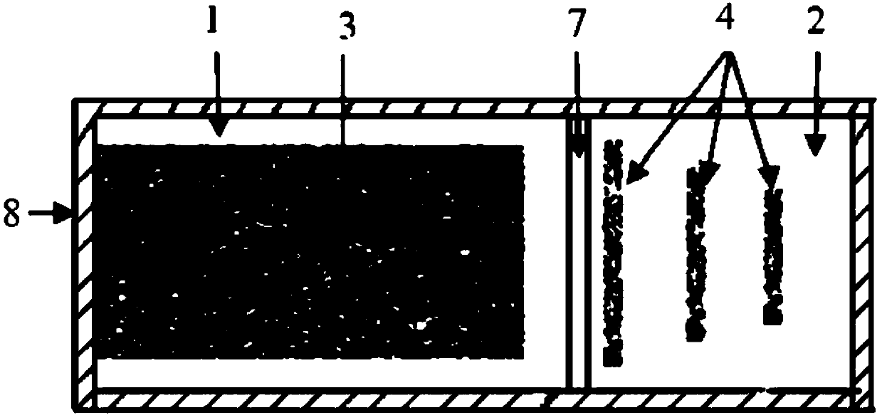
[0037] like Figures 1 to 2 shown. The invention discloses a micro loop heat pipe, which comprises an evaporation chamber, one end of the evaporation chamber is connected to the inlet of the condensation chamber through a steam pipe 5, and the other end of the evaporation chamber is connected to the outlet of the condensation chamber through a liquid return pipe 6; the evaporation chamber is filled with nano Fluid working medium;

[0038] The inside of the evaporation chamber is divided into two interconnected evaporation spaces 1 and reflux liquid storage spaces 2 through a heat-insulating partition 7 made of heat-insulating material;

[0039] In the evaporation space 1 and the return liquid storage space 2, there are respectively provided with multiple layers of capillary core layers with different apertures; the planes of the capillary core layers in the evaporation space 1 and the return liquid storage space 2 are perpendicular to each other;

[0040] When the external h...


PUM


Abstract

The invention discloses a micro loop heat pipe and a method. The micro loop heat pipe comprises an evaporation chamber. One end of the evaporation chamber is connected with an inlet of a condensing chamber through a steam pipe. The other end of the evaporation chamber is connected with an outlet of the condensing chamber through a liquid backflow pipe. The interior of the evaporation chamber is partitioned into an evaporation space and a backflow liquid storage space communicating with the evaporation space through a thermal insulating partition plate made of a thermal insulating material. A plurality of layers of capillary cores with different hole diameters are arranged in each of the evaporation space and the backflow liquid storage space. When external heat is input through the wall surface of the evaporation space, a nano fluid working medium in the evaporation space is heated and evaporated to generate steam; and the steam enters the condensing chamber through the steam pipe andis condensed, then flows back to the backflow liquid storage space along the liquid backflow pipe, and then returns to the evaporation space through the bottom of the evaporation chamber, namely a bottom channel of the thermal insulating partition plate; and circulation is achieved in this way.

Description

technical field [0001] The invention relates to heat pipes, in particular to a micro-loop heat pipe and method. Background technique [0002] The reliability of electronic equipment is extremely sensitive to temperature, and the reliability will drop by 5% for every 1°C increase in device temperature at the level of 70-80°C. Therefore, the internal heat dissipation problem of electronic components is particularly prominent. The failure caused by high temperature accounts for 50% of all electronic product failures, and heat dissipation has become a bottleneck in the development of miniaturization of electronic products. [0003] Miniature Loop Heat Pipe (mLHP) consists of five parts: evaporation chamber, condensation chamber, liquid storage chamber, steam pipe and liquid pipe, and mainly relies on capillary structure to provide circulating power for fluid working medium. This type of heat pipe has the advantages of large heat transfer power, good isothermal performance, high...

Claims


Application Information

Patent Timeline
Patent Type & Authority Applications(China)
IPC IPC(8): F28D15/04
CPCF28D15/043F28D15/046
Inventor 王小伍郑立贤黄敏兴范素芹
Owner SOUTH CHINA UNIV OF TECH
Why Eureka
Try Eureka