
Broadband low-profile dielectric resonator antenna based on two-dimensional periodic structure

A dielectric resonator, two-dimensional periodic technology, used in resonant antennas, antennas, electrical short antennas, etc., can solve the problems of low gain, large antenna size, and increase antenna size, etc., to achieve high gain, small plane size, low The effect of the section

Active Publication Date: 2018-02-13
NANTONG UNIVERSITY +1
View PDF2 Cites 13 Cited by
  • Summary
  • Abstract
  • Description
  • Claims
  • Application Information

AI Technical Summary

Problems solved by technology

As far as the dielectric resonator is concerned, there are many technical means to expand its operating bandwidth, for example, the impedance bandwidth can be broadened by introducing a parasitic dielectric resonator (Dielectric Resonator, DR) unit, but the problem brought by this method is that it increases the The size of the antenna; modifying the shape of the DR can also increase the bandwidth of the antenna, but some shapes are not easy to process and manufacture due to specificity, and this type of antenna usually has low gain due to the deterioration of the pattern performance; by combining the fundamental mode and along The three-mode mode in the plane direction can realize a wide-band, low-profile stacked DRA, but because it shifts the three-mode mode into the frequency band by amplifying the aspect ratio, the antenna has a relatively large plane size, which is not conducive to the antenna array design

Method used


Image

  • Broadband low-profile dielectric resonator antenna based on two-dimensional periodic structure
  • Broadband low-profile dielectric resonator antenna based on two-dimensional periodic structure
  • Broadband low-profile dielectric resonator antenna based on two-dimensional periodic structure

Examples


Embodiment Construction

[0017] In order to facilitate the understanding of the present invention, the present invention will be described more fully below with reference to the associated drawings. Typical embodiments of the invention are shown in the drawings. However, the present invention can be embodied in many different forms and is not limited to the embodiments described herein. Rather, these embodiments are provided so that the disclosure of the present invention will be thorough and complete.

[0018] It should be noted that the terms "vertical", "horizontal", "left", "right" and similar expressions used herein are for illustrative purposes only.

[0019] Unless otherwise defined, all technical and scientific terms used herein have the same meaning as commonly understood by one of ordinary skill in the technical field of the invention. The terms used herein in the description of the present invention are for the purpose of describing specific embodiments only, and are not intended to limit...


PUM


Abstract

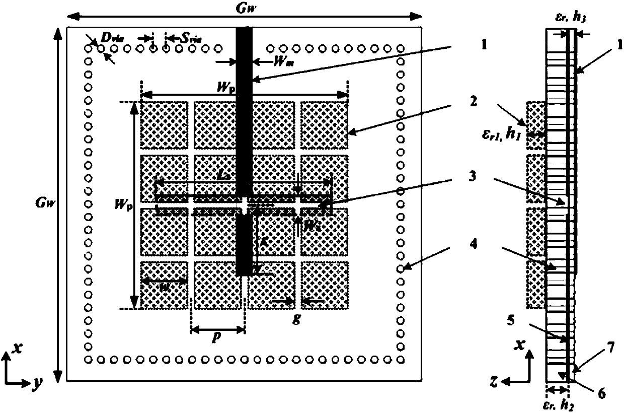
The invention discloses a broadband low-profile dielectric resonator antenna based on a two-dimensional periodic structure. The antenna comprises a first substrate, a second substrate located under the first substrate, and a dielectric resonator unit located above the first substrate for expanding the bandwidth,wherein, a microstrip feed line is disposed on a lower surface of the second substrate,a coupling feed slot perpendicular to the microstrip feed line is formedin an upper surface of the second substrate, a plurality of metalized through holes are formed around the dielectric resonatorunit, the metalized through holes penetrate the first substrate and the second substrate to form a substrate integrated waveguide back cavity, and the dielectric resonator unit includes a plurality ofdielectric sub-blocks spaced apart from each other in an array. The antenna has the characteristics of low profile and small plane size while satisfying the broadband, and is suitable for antenna array design.

Description

technical field [0001] The invention relates to the field of wireless communication, in particular to a wide-band low-profile dielectric resonator antenna based on a two-dimensional periodic structure. Background technique [0002] The rapid development of wireless communication technology puts forward higher requirements for the miniaturization, broadband and low loss performance of the antenna. Dielectric Resonator Antenna (DRA) has broad application prospects in modern wireless communication systems due to its low loss, high radiation efficiency and high design flexibility. [0003] Modern wireless communication systems have an urgent need for antennas with excellent characteristics such as broadband, compact structure, and high gain. As far as the dielectric resonator is concerned, there are many technical means to expand its operating bandwidth, for example, the impedance bandwidth can be broadened by introducing a parasitic dielectric resonator (Dielectric Resonator, ...

Claims


Application Information

Patent Timeline
Patent Type & Authority Applications(China)
IPC IPC(8): H01Q1/36H01Q9/04
CPCH01Q1/36H01Q9/0485
Inventor 杨汶汶董星妤陈建新唐慧施金孙闻剑
Owner NANTONG UNIVERSITY
Learn More