
Motorized spindle

A technology for electric spindles and spindles, which is applied to metal processing machinery parts, maintenance and safety accessories, driving devices, etc. It can solve the problems of reduced service life of spindles, high local temperature of bearings, damage, etc., so as to prolong service life and improve operation accuracy , The effect of smooth oil and gas flow

Active Publication Date: 2018-02-16
GUANGZHOU HAOZHI ELECTROMECHANICAL
View PDF5 Cites 9 Cited by
  • Summary
  • Abstract
  • Description
  • Claims
  • Application Information

AI Technical Summary

Problems solved by technology

The electric spindle has the characteristics of high-speed operation. Manufacturing errors, installation errors and overload may cause increased friction at the spindle bearing, which will lead to bearing wear, spindle heating and other problems, thus greatly reducing the service life of the spindle.
At present, oil-air lubricated electric spindles generally have the problems of uneven lubrication and unsmooth flow of oil and air, resulting in poor lubrication effect and high local temperature of the bearing; and the use of central water outlet cooling can effectively reduce the temperature of the electric spindle, but the cutting fluid may break through the sealing structure and cause pollution. Spindle, causing damage

Method used


Image

  • Motorized spindle
  • Motorized spindle
  • Motorized spindle

Examples


Embodiment Construction

[0038]Below, the invention will be further described in conjunction with the accompanying drawings and specific implementation methods. It should be noted that, on the premise of no conflict, the various embodiments described below or the technical features can be combined arbitrarily to form a new embodiment. .

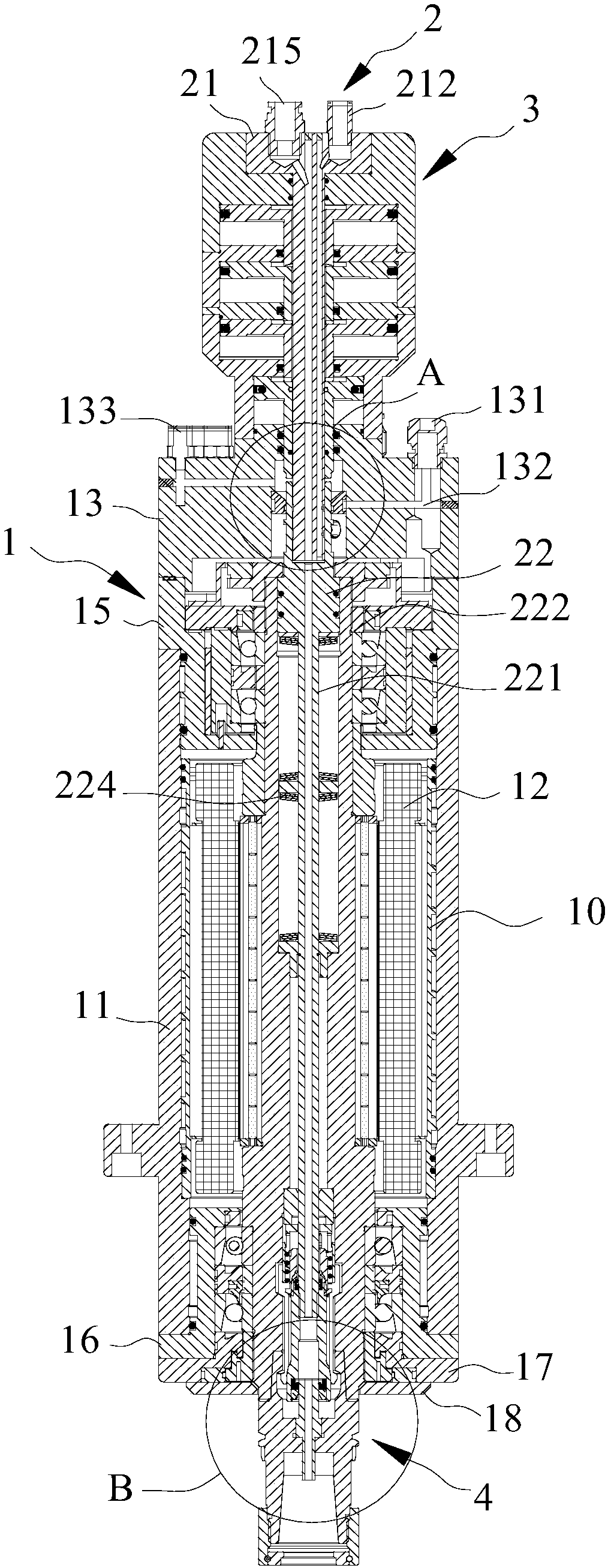
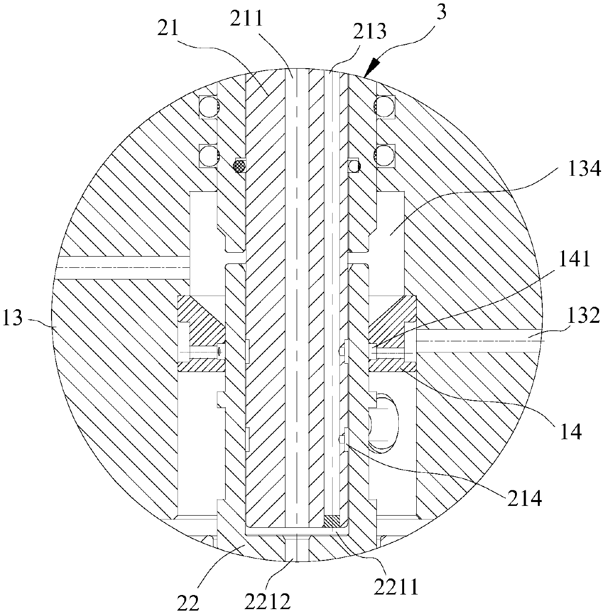
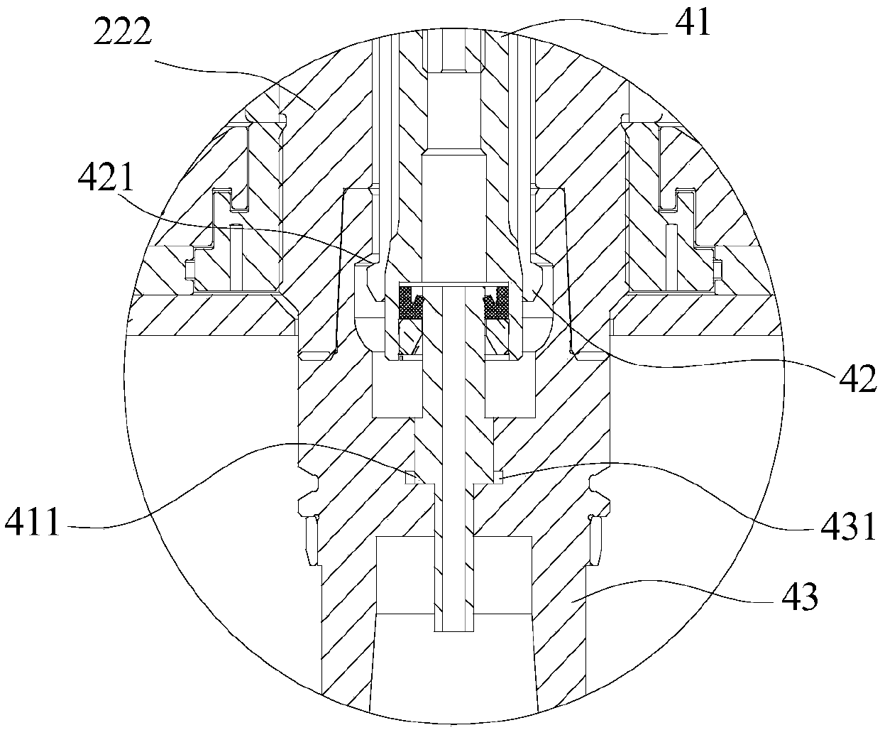
[0039] As attached to the manual figure 1 As shown, an electric spindle includes a spindle system assembly 1, a shaft core assembly 2, and a tool change cylinder assembly 3. The spindle system assembly 1 includes a body assembly 11, a stator 12, a molten steel jacket assembly 13, an upper bearing assembly 15, and a lower bearing assembly 16. The body lower cover assembly 17, the dust cover 18, the stator 12 is set inside the body assembly 11, the shaft core assembly 2 penetrates the stator 12; the upper part of the spindle system assembly 1 is provided with a tool change cylinder assembly 3; the steel water jacket assembly 13 is located in the spindle system The upp...


PUM


Abstract

The invention relates to a motorized spindle. The motorized spindle comprises a spindle system assembly, a shaft core assembly, a tool changing air cylinder assembly and a tool installing assembly; the tool changing air cylinder assembly is arranged at the upper portion of the spindle system assembly, and the tool installing assembly is arranged at the lower portion of the shaft core assembly; thespindle system assembly comprises a machine body assembly and a stator, the stator is arranged inside the machine body assembly, and the shaft core assembly penetrates the stator; the shaft core assembly comprises a center water outlet guide body and a core shaft which are sequentially connected, the middle portions of the center water outlet guide body and the core shaft are provided with channels used for cooling water circulation, a first pressure groove for high pressure gas is formed in the connecting position of the center water outlet guide body and the core shaft, and the spindle system assembly further comprises an upper bearing assembly and a lower bearing assembly; the upper bearing assembly, the machine body assembly and the lower bearing assembly are sequentially connected; and the upper bearing assembly and the lower bearing assembly are provided with oil spraying holes. According to the motorized spindle, the spindle running accuracy is improved, the spindle service life is prolonged, cooling water is effectively prevented from entering the interior of the spindle, and the spindle runs efficiently and stably.

Description

technical field [0001] The invention relates to the electromechanical field, in particular to an electric spindle. Background technique [0002] The electric spindle is a new technology in the field of CNC machine tools that integrates the machine tool spindle and the spindle motor. The electric spindle is usually composed of a shellless motor, a spindle, a bearing, a spindle unit shell, a drive module, and a cooling device. The electric spindle has the characteristics of high-speed operation. Manufacturing errors, installation errors and overload may cause increased friction at the spindle bearing, which will lead to bearing wear, spindle heating and other problems, thus greatly reducing the service life of the spindle. At present, oil-air lubricated electric spindles generally have the problems of uneven lubrication and unsmooth flow of oil and air, resulting in poor lubrication effect and high local temperature of the bearing; and the use of central water outlet cooling c...

Claims


Application Information

Patent Timeline
IPC IPC(8): B23Q5/14B23Q11/10
CPCB23Q5/147B23Q11/1023
Inventor 冯尚雄何权富汤秀清
Owner GUANGZHOU HAOZHI ELECTROMECHANICAL
Learn More