Drive-by-wire hydraulic brake system using liquid high pressure source generator

A hydraulic brake and generator technology, applied in the direction of brakes, brake-by-wire brakes, brake transmissions, etc., can solve the problem that the braking system cannot be applied to electric vehicles, the life of the high-voltage accumulator is limited, and the braking system is harmful. problems, to avoid frequent replacement of high-pressure accumulators, low failure probability, and eliminate life-limited effects

Inactive Publication Date: 2018-02-16
JILIN UNIV
View PDF12 Cites 8 Cited by
  • Summary
  • Abstract
  • Description
  • Claims
  • Application Information

AI Technical Summary

Problems solved by technology

[0008] In order to solve the following technical problems existing in the prior art: first, the existing brake system mostly depends on the vacuum degree of the engine so that the brake system cannot be applied to electric vehicles; The main cylinder or auxiliary master cylinder has problems such as high noise and slow response speed; third, when some wire-controlled brake systems use a motor to drive a pump to charge the high-pressure accumulator, the pressure pulsation inside the system will harm the brake system. Large, and the life of the high-pressure accumulator is limited, and it needs to be replaced frequently

Method used


Image

  • Drive-by-wire hydraulic brake system using liquid high pressure source generator
  • Drive-by-wire hydraulic brake system using liquid high pressure source generator
  • Drive-by-wire hydraulic brake system using liquid high pressure source generator

Examples


Embodiment Construction

[0043] The technical scheme of the present invention will be further explained and described below in combination with the accompanying drawings in the form of specific embodiments.

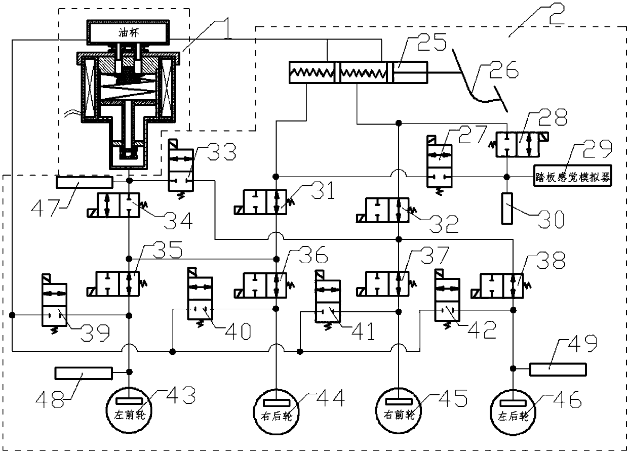
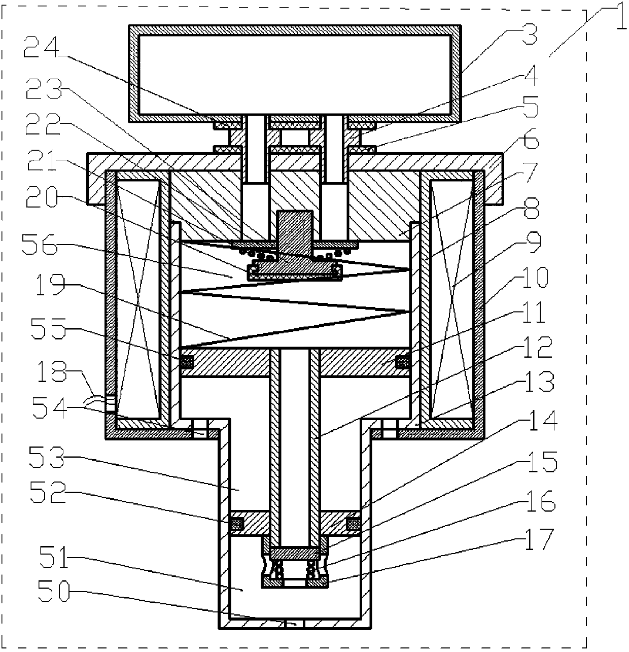
[0044] refer to figure 1 According to the present invention, the on-line hydraulic braking system of a liquid high-pressure source generator is composed of a liquid high-pressure source generator 1 and an actuator 2 of the brake-by-wire system.

[0045] The brake-by-wire system executive mechanism 2 is composed of a brake master cylinder 25, a brake pedal 26, a front cavity simulator coupled with a normally closed valve 27, a rear cavity simulator coupled with a normally closed valve 28, a pedal feeling simulator 29, a pedal pressure Sensor 30, front cavity simulator coupling normally open valve 31, rear cavity simulator coupling normally open valve 32, generator first liquid outlet valve 33, generator second liquid outlet valve 34, left front booster valve 35, right rear booster valve Pressure ...


PUM


Abstract

The invention discloses a drive-by-wire hydraulic braking system using a liquid high pressure source generator, and belongs to the technical field of vehicle drive-by-wire brake. The problems that a power assisting form of an existing brake system mostly depends on the vacuum degree of an engine, so that the existing brake system cannot be applied to an electric vehicle; when parts of drive-by-wire brake systems adopt a motor to assist power and brake a main cylinder or an auxiliary main cylinder directly, noise is large, and the responding speed is low; when the parts of drive-by-wire brake systems adopt the motor to drive a pump to supply liquid to a high pressure energy accumulator, damage to the braking system by pulsation with internal pressure is large, and the life of the high pressure energy accumulator is limited, so that frequent replacing is required are solved. The drive-by-wire hydraulic brake system is a mechanical device which uses electromagnetic force to drive a pistonto move and continuously produce the high pressure brake fluid, so that the drive-by-wire brake system is free from shackle of a vacuum power booster, the motor, the pump and the high pressure energyaccumulator, the structure is simpler, the integration degree is higher, and meanwhile the drive-by-wire brake system has the functions of fast active pressure buildup, accurate pressure adjusting, low vibration noise, failure protection, full decoupling of pedal force and the like.

Description

technical field [0001] The invention belongs to the technical field of automotive brake-by-wire. Background technique [0002] The improvement of the braking system in the prior art mainly lies in the energy source of the system. Since the entire braking system has no external energy support, it is difficult to meet the braking force required by the braking system only by the braking force of the driver pedaling, so it is necessary to provide a braking energy source for the braking system. The most common Add a vacuum booster to the brake master cylinder, and use the vacuum of the engine to boost the braking system. Due to its simple structure and stable performance, it has dominated the braking system industry for many years. With the development of new energy vehicles and smart vehicles, new requirements are put forward for the automotive braking system: to reduce and cancel the dependence on engine vacuum; so it is necessary to find new energy sources for the braking sys...

Claims


Application Information

Patent Timeline
Patent Type & Authority Applications(China)
IPC IPC(8): B60T13/12B60T8/40
CPCB60T8/4081B60T13/12B60T2270/82
Inventor 李静丁明慧谷贺冲何闫
Owner JILIN UNIV
Why Eureka
Try Eureka