Large-size optical film automatic feeding device

A technology of automatic feeding and optical film, which is applied in the direction of thin material handling, transportation and packaging, and object separation, etc. It can solve problems such as unsmooth operation process, high work intensity, and visual fatigue, so as to improve the smoothness of operation process and improve The effect of work efficiency and broad market prospect

Pending Publication Date: 2018-02-16
SHENZHEN JINGCHUANG TECH CO LTD
View PDF7 Cites 9 Cited by
  • Summary
  • Abstract
  • Description
  • Claims
  • Application Information

AI Technical Summary

Problems solved by technology

[0003] For the loading of large-size optical films before cutting, the existing methods are manual loading, and the operators pick up the processed optical films one by one and place them on the conveyor belt of the quality inspection equipment in sequence. This feeding method requires a lot of manpower, and the feeding speed is slow, the work efficiency is low, and the work intensity is high. In addition, due to the static electricity between the optical films, there is easy to exist between each other. Therefore, the operator is placing the optical film. At the same time, carefully observe to ensure that only one piece of optical film is placed on the conveyor belt at a time. Manual work for a long time can easily cause visual fatigue, resulting in the undesirable phenomenon of placing multiple pieces of optical film on the conveyor belt at a time, resulting in unsmooth operation process and affecting the optical film. Quality Inspection

Method used


Image

  • Large-size optical film automatic feeding device
  • Large-size optical film automatic feeding device
  • Large-size optical film automatic feeding device

Examples


Embodiment Construction

[0025] The following description serves to disclose the present invention to enable those skilled in the art to carry out the present invention. The preferred embodiments described below are only examples, and those skilled in the art can devise other obvious variations. The basic principles of the present invention defined in the following description can be applied to other embodiments, variations, improvements, equivalents and other technical solutions without departing from the spirit and scope of the present invention.

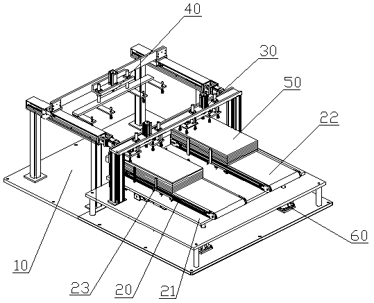
[0026] figure 1 It shows a structural schematic diagram of an embodiment of the large-size optical film automatic feeding device of the present invention, and is also a schematic diagram of a preferred embodiment. Such as figure 1 As shown, the optical film automatic feeding device described in this embodiment includes a base 10, a feeding mechanism 20, a suction mechanism 30, a feeding mechanism 40 and a control mechanism (not shown in the figure), the...


PUM


Abstract

The invention belongs to the field of optical automation test and especially relates to a large-size optical film automatic feeding device which comprises a base, a feeding mechanism, an absorbing mechanism, a transporting mechanism and a control mechanism. The base is used for carrying the feeding mechanism above the base, and the feeding mechanism is arranged on the base so as to carry optical films and transmit the optical films to a first working station. The absorbing mechanism which can move up and down is arranged above the first working station so as to absorb the optical films in thefeeding mechanism and transmit the absorbed optical films to a second working station. The transporting mechanism which can move up and down is arranged at the rear end of the absorbing mechanism so as to absorb the optical films on the second working station and transmit the absorbed optical films to a third working station. The control mechanism is electrically connected with the feeding mechanism, the absorbing mechanism and the transporting mechanism respectively. When in use, operators only need to place stacked optical films on the feeding mechanism, bath feeding can be easily realized.The large-size optical film automatic feeding device is time-saving and labor-saving, high in working efficiency and smooth in operating process, and can be applied to assembly line work environment and has a broad market prospect.

Description

technical field [0001] The invention belongs to the field of optical automatic detection, in particular to a large-size optical film automatic feeding device. Background technique [0002] Optical film is composed of thin layered medium, a type of optical medium material that transmits light through the interface, usually refers to the film used as a component of optical device and other optical purposes, the application of optical film began in the 1930s. Nowadays, optical films have been widely used in the fields of optics and optoelectronics to manufacture various optical instruments, and various optical films are used in optical devices such as image display devices, and a representative example is polarizing plates used in liquid crystal display devices. A polarizing plate is usually a laminated optical film in which a protective film is attached to at least one surface of a polarizing film. Moreover, the polarizing film which comprises a polarizing plate, and a protec...

Claims


Application Information

Patent Timeline
Patent Type & Authority Applications(China)
IPC IPC(8): B65H1/08B65H3/08B65H5/08B65H7/02
CPCB65H1/08B65H3/0816B65H5/08B65H7/02B65H2701/1131B65H2406/34B65H2405/10
Inventor 陈志忠彭朝东林文华林飞曾勇展
Owner SHENZHEN JINGCHUANG TECH CO LTD
Why Eureka
Try Eureka