Branch air film hole structure for air cooling turbines

A technology of air film holes and branch holes, which is applied in the direction of blade support components, engine components, machines/engines, etc., can solve the problems of small cold air coverage area and insufficient lateral diffusion ability of cold air film, and achieve the expansion of lateral coverage area, Strong economy and engineering practicability, and the effect of suppressing uplift

Active Publication Date: 2018-02-16
INST OF ENGINEERING THERMOPHYSICS - CHINESE ACAD OF SCI
View PDF6 Cites 11 Cited by
  • Summary
  • Abstract
  • Description
  • Claims
  • Application Information

AI Technical Summary

Problems solved by technology

However, the shortcoming of the branch-type air film hole structure is that the lateral diffusion ability of the cold air film is insufficient, resulting in a small coverage area of ​​cold air, and the utilization rate of cold air needs to be further improved. In addition, the branch-type air film hole structure is being arranged Limited by its special branch structure, it can only be arranged in a non-staggered way

Method used


Image

  • Branch air film hole structure for air cooling turbines
  • Branch air film hole structure for air cooling turbines
  • Branch air film hole structure for air cooling turbines

Examples


Embodiment Construction

[0032] In order to make the object, technical solution and advantages of the present invention clearer, the present invention will be further described in detail below with reference to the accompanying drawings and examples. It should be noted that the following descriptions are only preferred implementation examples of the present invention, and therefore do not limit the protection scope of the present invention.

[0033] Unless defined otherwise, technical and scientific terms used herein have the same meaning as commonly understood by one of ordinary skill in the art to which this invention belongs. If ranges are disclosed, the endpoints of all ranges referring to the same element or property are inclusive and independently combinable. The modifier "about" used in conjunction with a quantity is inclusive of a stated value and has the meaning dictated by the context (eg, including the degree of error associated with measurement of the particular quantity).

[0034] figu...


PUM


Abstract

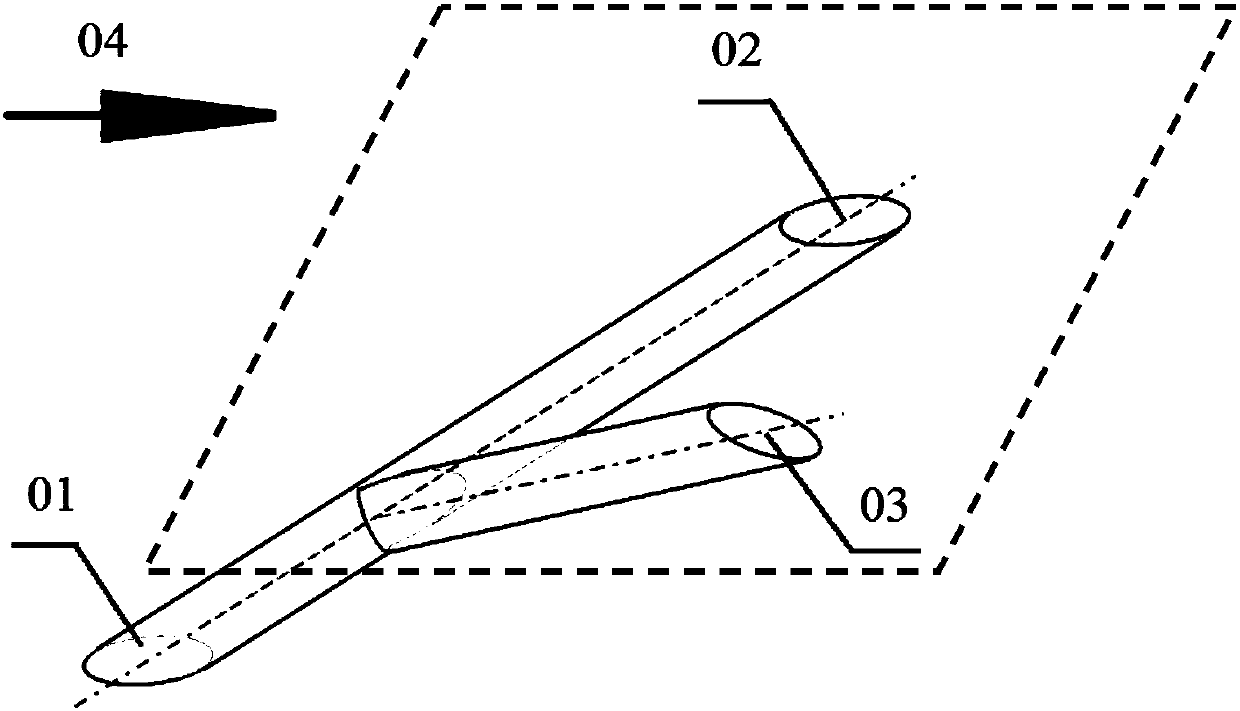
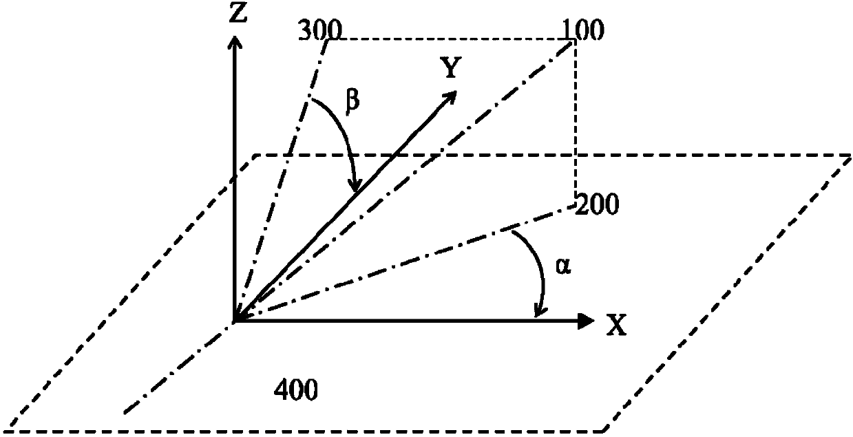
The invention discloses a branch air film hole structure for air cooling turbines. The branch air film hole structure is applicable to air film cooling for cooling hot-end components of gas turbine engines and comprises a plurality of branch air film hole units. The branch air film hole units are arranged on cooled wall surfaces, and each branch air film hole unit comprises a main hole passage anda branch hole passage which obliquely laterally extends out of the middle of a main hole. The branch air film hole structure has the advantages that included angles in expansion directions opposite to flow directions of main flow are formed between the main hole passages and the main flow and between the branch hole passages and the main flow, reverse-kidney-shaped vortex pairs can be formed by two branches of cold air jet flow under entrainment and mutual interference effects of the main flow, accordingly, vortex system structures are favorable for enlarging the transverse cover areas of cold air, hot air can be effectively prevented from being drawn into the lower side from two sides of each cold air film, the adhesive ability of the cold air films can be improved, and air film coolingeffects can be improved; the branch air film hole structure is high in air film cooling efficiency as compared with cylindrical holes and is obviously superior under the condition of high blowing ratios; the branch air film hole structure is mainly cylindrical and has a high practical engineering value, and technologies for processing the branch air film hole structure are simple.

Description

technical field [0001] The invention belongs to the cooling field of high-temperature components such as combustion chambers and turbines, and relates to a gas film hole structure, in particular to a branched gas film hole structure of an air-cooled turbine, which is mainly used for cooling high-temperature components such as combustion chambers and turbines of gas turbines . Background technique [0002] The working temperature of modern gas turbine engines continues to increase, which puts forward extremely high requirements on the heat resistance of the materials of the hot end parts. However, only by improving the heat resistance of materials can no longer meet the demand. High-temperature components such as casings are equipped with film cooling structures. Film cooling extracts high-pressure cold air from the compressor end and transports it to hot-end components (such as combustion chambers, turbine blades, casings, etc.) The air film hole is sprayed out, and the col...

Claims


Application Information

Patent Timeline
Patent Type & Authority Applications(China)
IPC IPC(8): F01D5/18
CPCF01D5/186
Inventor 唐菲赵庆军隋秀明赵巍雒伟伟
Owner INST OF ENGINEERING THERMOPHYSICS - CHINESE ACAD OF SCI
Why Eureka
Try Eureka