Oil pan and engine

A technology for oil pans and oil passages, applied to oil pans, engine components, machines/engines, etc., can solve problems such as increased fuel consumption, large resistance, and high order noise, and reduce oil passage resistance loss, The effect of reducing the chance of resonance and reducing the noise level

Active Publication Date: 2020-07-24
BEIQI FOTON MOTOR CO LTD
View PDF4 Cites 0 Cited by
  • Summary
  • Abstract
  • Description
  • Claims
  • Application Information

AI Technical Summary

Problems solved by technology

[0002] The oil pan is used to seal the crankcase of the engine and store a certain amount of engine oil. The lubrication and cooling of the engine requires clean and temperature-appropriate engine oil. When the temperature is low, the oil has a higher viscosity and greater resistance, which makes the engine run at cold start and low temperature. The mechanical efficiency is low in the early stage of environmental operation, which increases the fuel consumption rate
In related technologies, the oil filter is difficult to arrange and not easy to replace. The longer the lubricating oil path of the engine, the greater the resistance of the lubrication system, and the greater the power loss of the engine and oil pump. The oil cooler is the only way for the oil, resulting in It is difficult for the engine to heat up, and the oil in the related technology first passes through the filter and then enters the oil cooler. The high-temperature oil enters the filter, which will cause premature damage to the filter element of the filter and shorten the replacement of the filter element. Period, and more and more oil pumps are arranged inside the oil pan to save the overall layout space, but this kind of layout has high order noise and poor driving experience for the driver, so there is room for improvement

Method used


Image

  • Oil pan and engine
  • Oil pan and engine
  • Oil pan and engine

Examples


Embodiment Construction

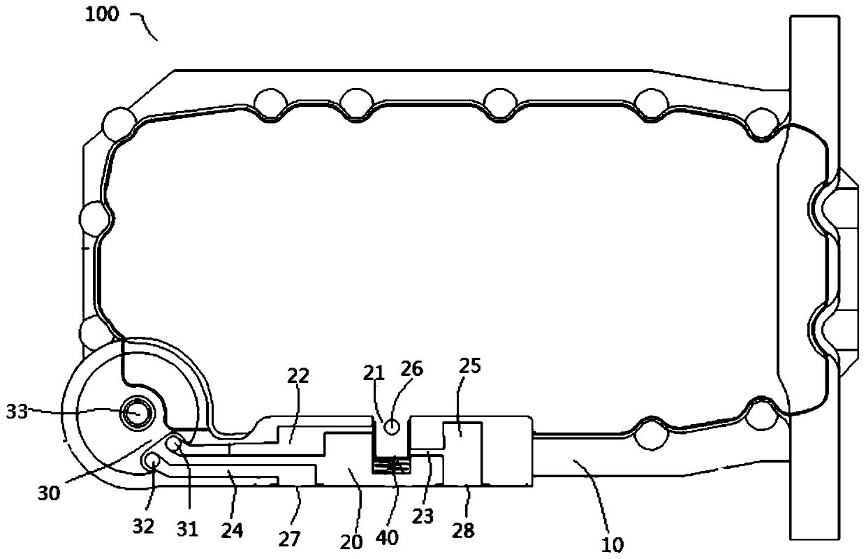
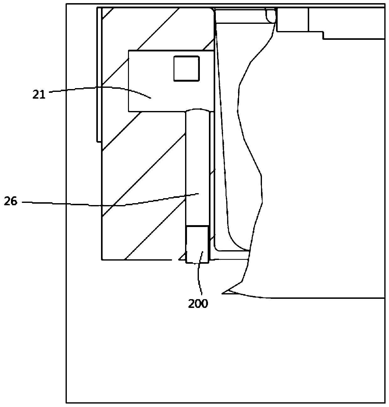
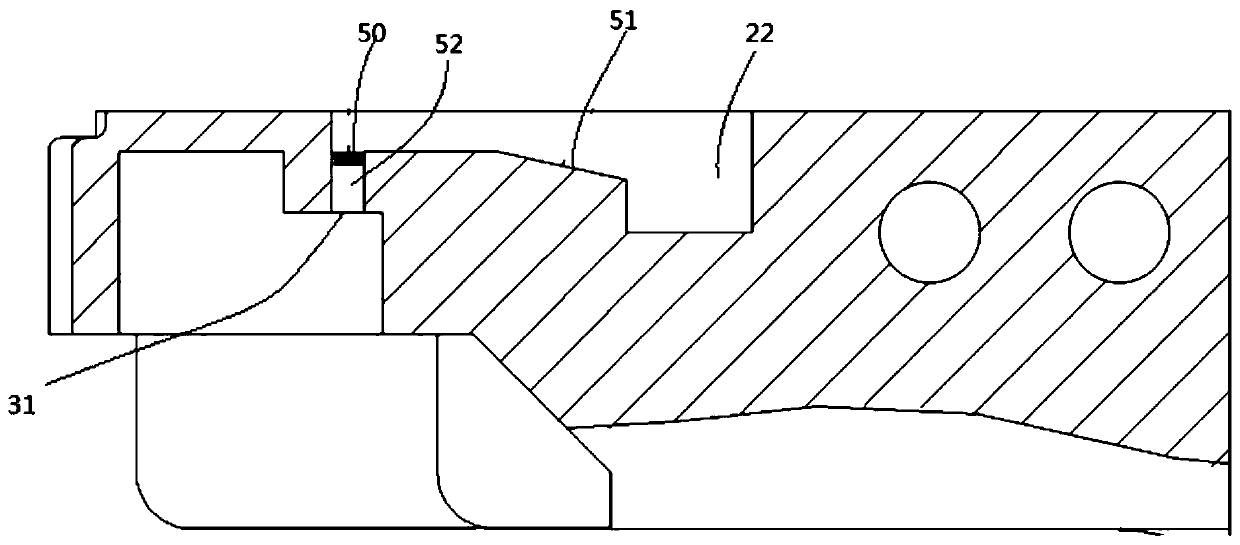
[0035] The embodiments of the present invention are described in detail below. Examples of the embodiments are shown in the accompanying drawings, in which the same or similar reference numerals indicate the same or similar elements or elements with the same or similar functions. The embodiments described below with reference to the drawings are exemplary, and are only used to explain the present invention, but should not be understood as limiting the present invention.

[0036] In the description of the present invention, it should be understood that the terms "center", "longitudinal", "transverse", "length", "width", "thickness", "upper", "lower", "front", " Back", "Left", "Right", "Vertical", "Horizontal", "Top", "Bottom", "Inner", "Outer", "Clockwise", "Counterclockwise", "Axial", The orientation or positional relationship indicated by "radial", "circumferential", etc. is based on the orientation or positional relationship shown in the drawings, and is only for the convenienc...


PUM


Abstract

The invention discloses an oil sump and an engine. The oil sump comprises a shell. The shell is provided with an engine oil cooler installing base and an engine oil filter installing base. The engineoil filter installing base is provided with an engine oil filter installing base oil way. The engine oil cooler installing base is provided with a first oil way connected with an oil outlet of an engine oil pump and a plurality of oil outlet branch ways connected with the first oil way. The engine oil filter installing base oil way is connected with one of the oil outlet branch ways, the other oneof the oil outlet branch ways is suitable for being connected with the engine oil filter installing base oil way through an engine oil cooler, and the first oil way selectively communicates with at least one of the two above oil outlet branch ways. According to the oil sump, the structure arrangement of the engine oil cooler installing base and the engine oil filter installing base is simple, engine oil filter replacement is convenient, the path that engine oil flows into the engine oil filter installing base can be flexibly selected according to the temperature of engine oil, the oil way resistance losses are reduced, and the noise level is lowered.

Description

Technical field [0001] The invention belongs to the technical field of vehicle manufacturing, and specifically relates to an oil pan and an engine provided with the oil pan. Background technique [0002] The oil pan is used to seal the crankcase of the engine and store a certain amount of oil. The lubrication and cooling of the engine require clean and suitable temperature oil. When the temperature is low, the oil has higher viscosity and higher resistance, which makes the engine cold start and low temperature The mechanical efficiency in the early stage of environmental operation is low, which increases the fuel consumption rate. In the related technology, the oil filter is difficult to arrange and not easy to replace. The longer the engine lubricating oil path, the greater the resistance of the lubrication system, and the greater the power loss of the engine and the oil pump. The oil cooler is the only way for the oil. It is difficult for the engine to heat up, and the oil in ...

Claims


Application Information

Patent Timeline
Patent Type & Authority Patents(China)
IPC IPC(8): F01M11/00F01M11/03
CPCF01M11/0004F01M11/03F01M2011/0012F01M2011/031
Inventor 李乐赵亮董志强袁秋实黄国伟
Owner BEIQI FOTON MOTOR CO LTD
Why Eureka
Try Eureka