
Vertical shaft-coupling throw searching technique for large-scale water turbine

A technology of hydraulic turbine shaft and process method, which is applied in the direction of adopting mechanical devices, mechanical measuring devices, measuring devices, etc., can solve the problems of affecting the installation period and manufacturing cost of the unit, affecting the accuracy of finding the pendulum, and the high weight of the coupling, so as to improve the construction site. Shaft accuracy and installation efficiency, reducing equipment requirements, and ensuring the effect of alignment accuracy

Active Publication Date: 2018-02-16
HARBIN ELECTRIC MASCH CO LTD
View PDF4 Cites 5 Cited by
  • Summary
  • Abstract
  • Description
  • Claims
  • Application Information

AI Technical Summary

Problems solved by technology

The swing of the horizontal car coupling is limited by the load capacity of the machine tool. The total weight of the coupling of some large units exceeds the load of the machine tool, so it is impossible to find the swing of the equipment. The joint boring on the construction site can only be performed after the swing of the coupling is found when the unit is installed on the construction site. Hole processing, and site boring will affect the installation cycle and manufacturing cost of the unit; in addition, even if the swing can be achieved in the large horizontal car coupling, due to the high weight of the coupling, the shafting after the coupling will produce a certain deflection. Affect the accuracy of finding the pendulum, or even make mistakes, resulting in readjustment of the construction site
Large-scale shaft coupling horizontal swing adjustment requires additional large-scale center frame and other tooling support devices, which requires higher tooling costs in manufacturing

Method used


Image

  • Vertical shaft-coupling throw searching technique for large-scale water turbine
  • Vertical shaft-coupling throw searching technique for large-scale water turbine
  • Vertical shaft-coupling throw searching technique for large-scale water turbine

Examples


Embodiment Construction

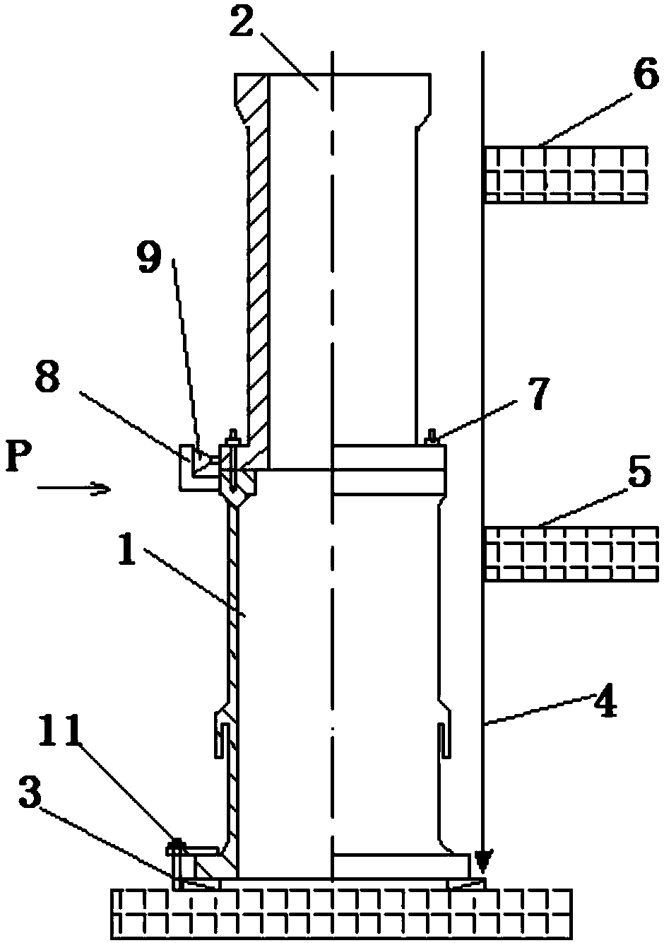
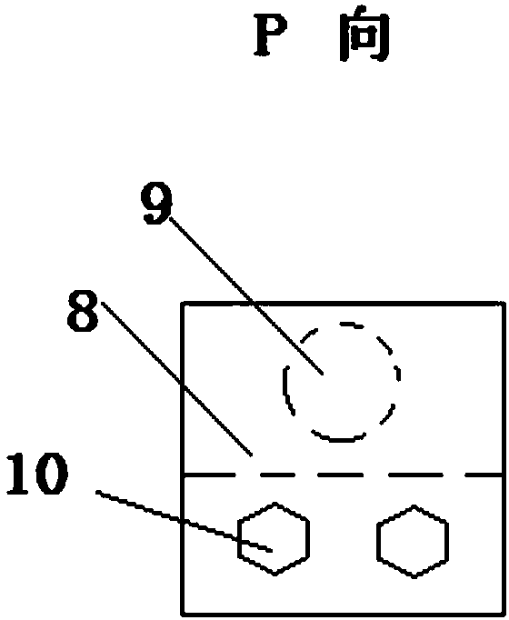
[0046] (1) Lift the turbine shaft 1 vertically and place it on a solid metal platform 12, see figure 1 . Pad the flange surface under the shaft in 4 groups, 2 in each group, a total of 8, and the adjustable shims 3 are evenly distributed, and the copper sheet is placed on the adjustable shims to protect the flange processing surface of the turbine shaft 1;

[0047] (2) Turbine shaft 1 is roughly leveled according to the processing surface on the back side of the flange, and the accuracy is not greater than 0.05mm / 1000mm, and the lower flange is pressed and fixed with the pressure plate and screw assembly 11. Hang the generator shaft 2 on the upper end of the turbine shaft 1. Align the flanges of the turbine shaft 1 and generator shaft 2 according to the finished seams and align the coupling holes, see figure 1 ;

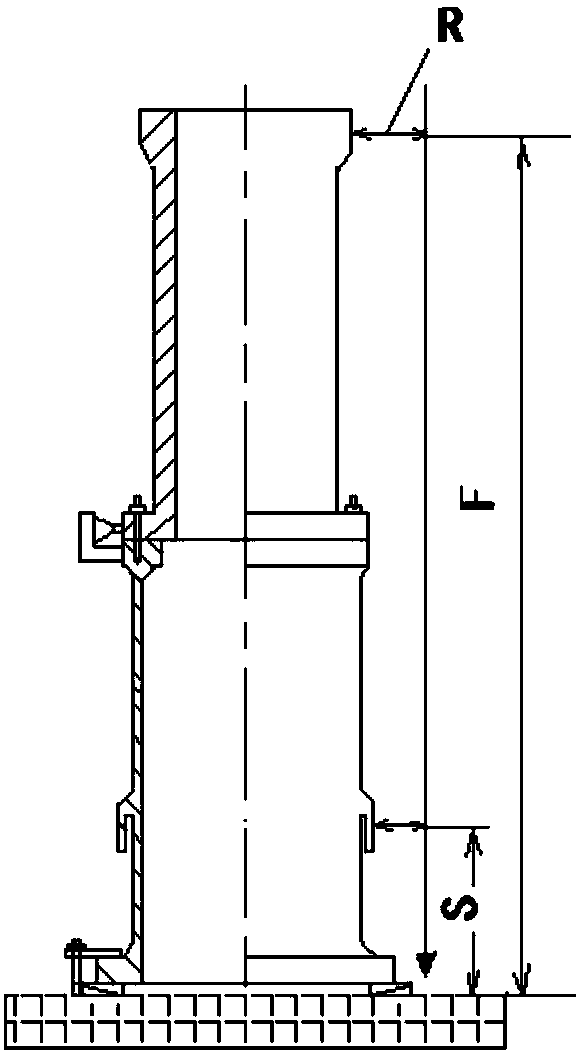
[0048] (3) Build a solid scaffolding platform 5 and platform 6 near the flange surface of the coupling combination and the upper flange surface of the generator s...


PUM


Abstract

The invention discloses a vertical shaft-coupling throw searching technique for a large-scale water turbine, and the technique comprises the steps: enabling a water turbine and a generator water turbine shaft (1) to achieve the vertical shaft coupling with a generator shaft (2), and adjusting the concentricity through a vertical method, thereby reducing the deflection, caused by a horizontal type,of the shaft, and improving the alignment precision; employing a counter point uniform distribution steel wire suspending method, precisely measuring the concentricity, and eliminating the system deviation through counter point measurement, thereby improving the precision; and reasonably setting an adjustment device at the external periphery of a shaft coupling flange surface. The technique doesnot occupy equipment, is simple in operation, is reliable in precision, overcomes a difficulty in the vertical adjustment after the shaft coupling of the generator water turbine shaft (1) and the generator shaft (2), improves the adjustment efficiency and precision, is novel, reasonable and simple, enables the machining quality to be controllable, and is high in precision.

Description

Technical field: [0001] The invention discloses a technique method for finding the swing of a vertical coupling of a large water turbine. Background technique: [0002] Turbine shafts and generator shafts are high-precision rotating parts of hydropower stations, and the coaxial precision of their shaft systems is related to the stable operation and service life of the unit. After the turbine shaft and the generator shaft are processed separately on the horizontal car in the manufacturing plant, it is usually necessary to couple the turbine shaft 1 and the generator shaft 2 and carry out shaft alignment. Shaft 2 coupling joint shaft holes are bored together at the specific position adjusted concentrically and the coupling flange joint holes are bored together. When installing on the construction site, the coupling joint holes are installed in the coupling pin bolts for positioning, so as to ensure that the turbine shaft 1 and the power generation Relative position of cranksh...

Claims


Application Information

Patent Timeline
IPC IPC(8): G01B5/00G01B5/252
Inventor 黄海玉李鑫葛军刘琦杨思晋唐勇
Owner HARBIN ELECTRIC MASCH CO LTD
Learn More