Method for measuring inductance in deep saturation state of transformer

A measurement method, technology of transformers, applied in the field of transformers

Active Publication Date: 2018-02-16
ELECTRIC POWER RES INST OF GUANGDONG POWER GRID
View PDF6 Cites 12 Cited by
  • Summary
  • Abstract
  • Description
  • Claims
  • Application Information

AI Technical Summary

Problems solved by technology

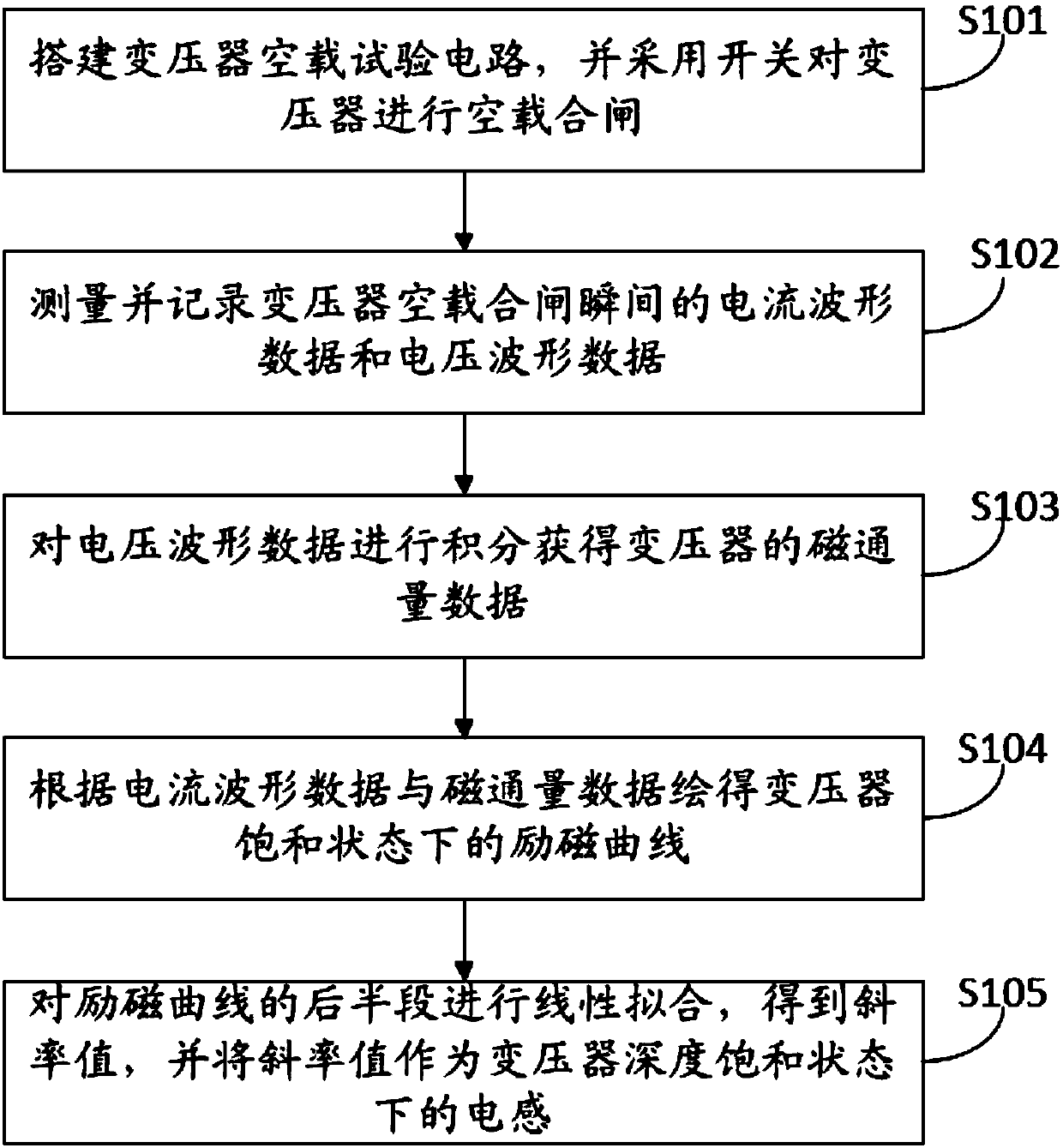
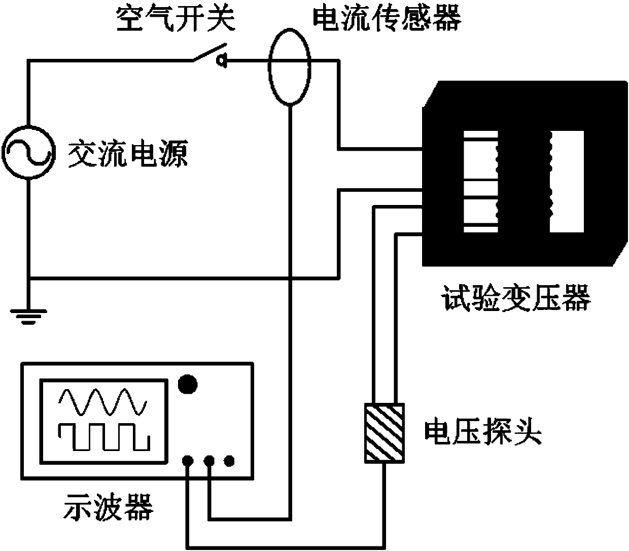
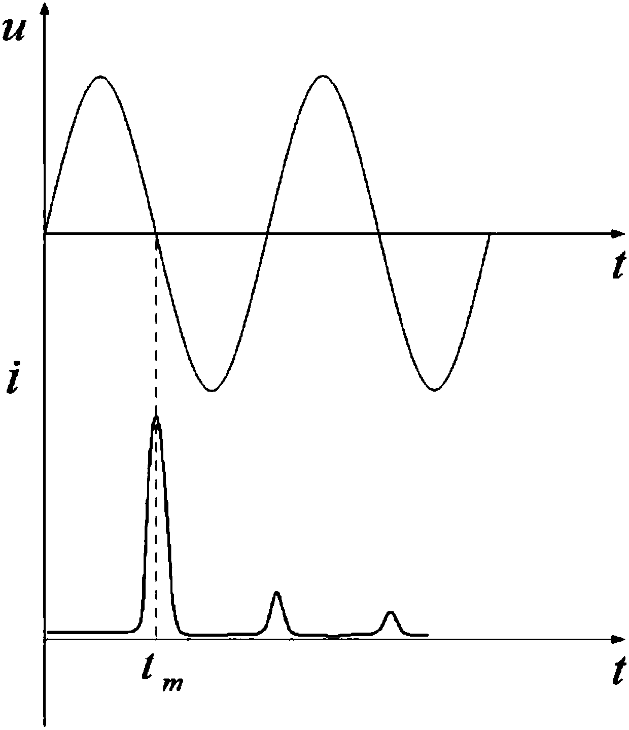
[0005] The embodiment of the present invention provides a method for measuring the inductance of a transformer in a deeply saturated state, which solves the technical problem that there is no method in the prior art that can simulate and obtain the operating state of a transformer in a deeply saturated state

Method used


Image

  • Method for measuring inductance in deep saturation state of transformer
  • Method for measuring inductance in deep saturation state of transformer
  • Method for measuring inductance in deep saturation state of transformer

Examples


Embodiment Construction

[0033] An embodiment of the present invention provides a method for measuring the inductance of a transformer in a deeply saturated state, which is used to solve the technical problem that there is no method in the prior art that can simulate and obtain the operating state of a transformer in a deeply saturated state.

[0034] In order to make the purpose, features and advantages of the present invention more obvious and understandable, the technical solutions in the embodiments of the present invention will be clearly and completely described below in conjunction with the accompanying drawings in the embodiments of the present invention. Obviously, the following The described embodiments are only some, not all, embodiments of the present invention. Based on the embodiments of the present invention, all other embodiments obtained by persons of ordinary skill in the art without making creative efforts belong to the protection scope of the present invention.

[0035] The invento...


PUM


Abstract

The invention discloses a method for measuring the inductance in the deep saturation state of a transformer. The method is used for solving the technical problem that in the prior art, no method is provided for simulating the running state of a transformer in a deep saturation state. According to the invention, the excitation surge current and the secondary side voltage of the transformer when thetransformer is in no-load and switched-on state are measured. Through the numerical integration and the calculation, the excitation curve of the transformer can be obtained. Meanwhile, the range of the excitation surge current is large, and the obtained excitation curve contains excitation characteristics in the deep saturation state. Therefore, the inductance of the transformer in the deep saturation state can be obtained by performing linear fitting on the obtained excitation curve. The operation state of the transformer in the deep saturation state can be studied by the engineering operation and maintenance personnel.

Description

technical field [0001] The invention relates to the technical field of transformers, in particular to a method for measuring the inductance of a transformer in a deeply saturated state. Background technique [0002] The transformer is a device that uses the principle of electromagnetic induction to change the AC voltage. The main components are the primary coil, the secondary coil and the iron core (magnetic core). Mainly used for: voltage conversion, current conversion, isolation and voltage regulation, etc. When an alternating current flows through the primary coil, an alternating magnetic flux is generated in the magnetic core, which induces a voltage (or current) in the secondary coil. Among them, the function of the magnetic core is mainly to form a magnetic circuit of coupled magnetic flux with small reluctance. Because of its small reluctance, the working efficiency of the transformer can be greatly improved. [0003] Under normal circumstances, when manufacturing t...

Claims


Application Information

Patent Timeline
Patent Type & Authority Applications(China)
IPC IPC(8): G01R27/26
CPCG01R27/2611
Inventor 周原司马文霞杨贤刘永来杨翠茹马志钦杨鸣彭代晓周丹吕鸿李谦
Owner ELECTRIC POWER RES INST OF GUANGDONG POWER GRID
Why Eureka
Try Eureka