High-efficiency stripping device for insulator of electric power communication cable conductor

A technology for communication cables and stripping equipment, which is applied to equipment for dismantling/armoring cables, cable installation, and cable installation devices. , the effect of reducing labor intensity and improving efficiency

Inactive Publication Date: 2018-02-16
倪菊莲
View PDF0 Cites 16 Cited by
  • Summary
  • Abstract
  • Description
  • Claims
  • Application Information

AI Technical Summary

Problems solved by technology

[0003] In order to solve the above problems, the present invention provides a high-efficiency stripping equipment for power communication cable insulators, which can solve the problem of manually stripping the insulator on the cable in the manual peeling method in the cable recovery process, and manually stripping the insulator on the cable. The efficiency is low. Manually stripping the insulation on the cable will affect the health of the human arm. Different tools are required to strip cables of different diameters. The operation is complicated. The incineration and chemical methods will directly damage the internal organization of the cable insulator and cannot be used for cable insulation. The insulator is used for secondary use, and the gas generated during the incineration process seriously pollutes the environment. The cable is composed of a variety of coils, and different coils need to be wound manually. Manual coil winding takes a long time, labor intensity is high, and work efficiency is low. , can realize the function of efficient stripping of cable insulation, without manual operation, will not affect the health of human arms, can be automatically adjusted for cables of different specifications, and has the advantages of simple operation, less time-consuming, low labor intensity and low work efficiency, etc. advantage

Method used


Image

  • High-efficiency stripping device for insulator of electric power communication cable conductor
  • High-efficiency stripping device for insulator of electric power communication cable conductor
  • High-efficiency stripping device for insulator of electric power communication cable conductor

Examples


Embodiment Construction

[0026] In order to make the technical means, creative features, goals and effects achieved by the present invention easy to understand, the present invention will be further described below in conjunction with specific illustrations.

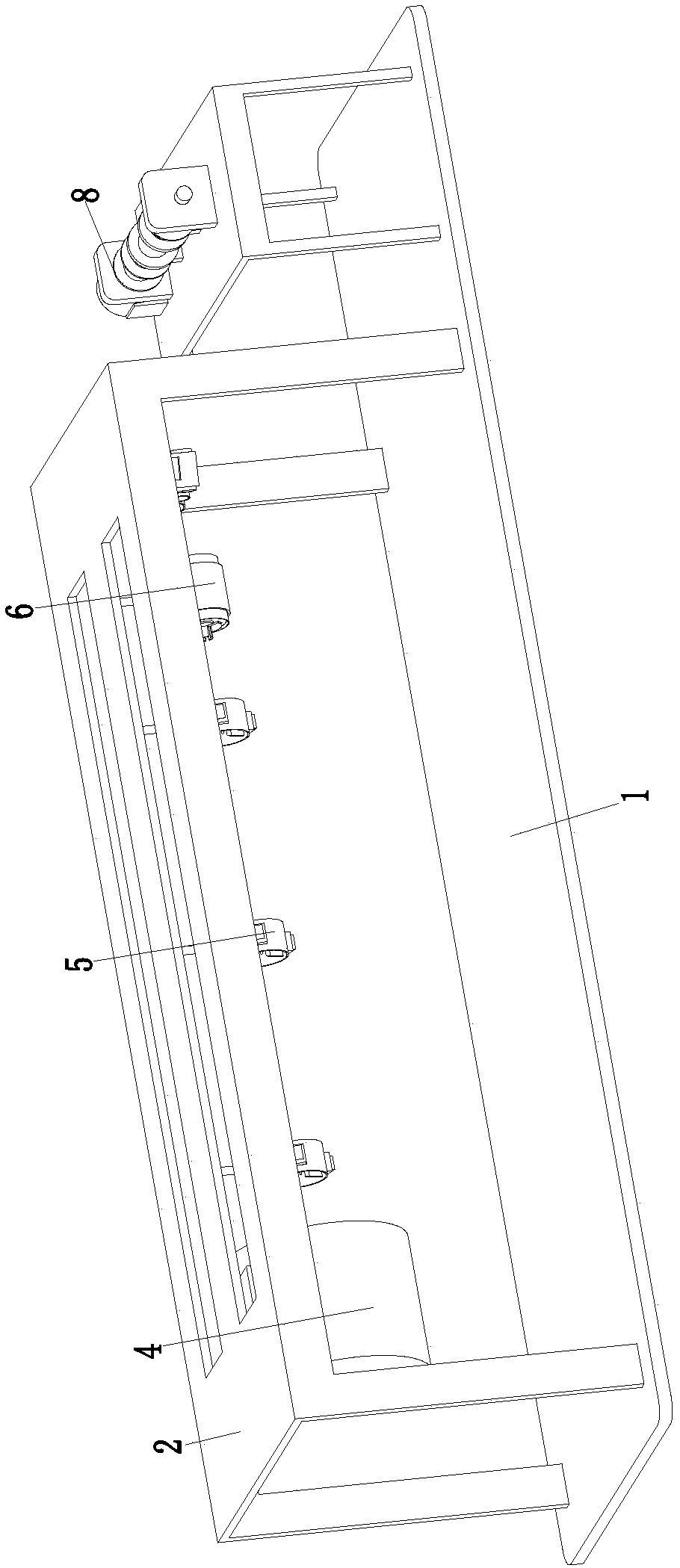
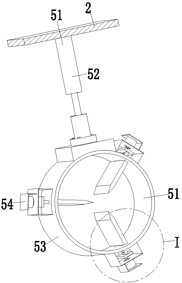
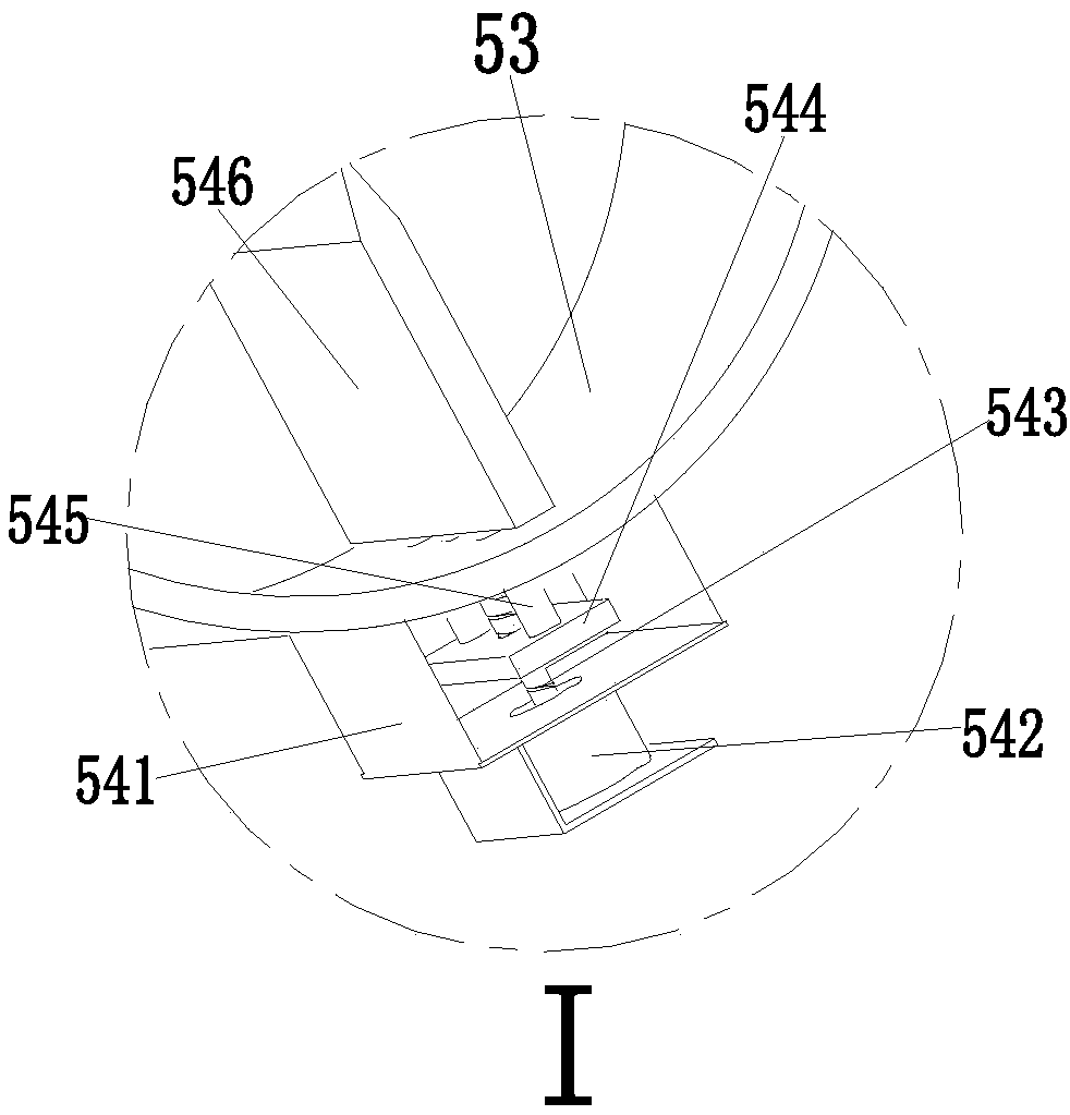
[0027] Such as Figure 1 to Figure 7 As shown, a high-efficiency stripping equipment for power communication cable insulation includes a base plate 1, a cutting support frame 2 is installed on the base plate 1, and the lower end of the cutting support frame 2 is sequentially installed with an adjusting skinning device 4, a dividing device 5 and Stripping and branching device 6, adjusting skin cutting device 4 can cut the insulator on the surface of the cable in sections, and the splitting device 5 can axially divide the insulator on the surface of the cable during work, and at the same time can make the coils of the cable Separated, the stripping and separating device 6 can separate the insulator on the cable, and at the same time can separate a...


PUM


Abstract

The invention relates to a high-efficiency stripping equipment for electric and communication cable insulators, which includes a bottom plate, a cutting support frame is installed on the bottom plate, and the lower end of the cutting support frame is sequentially installed with an adjusting skinning device, a dividing device and a stripping and separating device, and the bottom plate A winding device is installed on the cable, and the present invention can solve the problem that the manual peeling method in the cable recycling process needs to manually peel off the insulator on the cable, and the efficiency of manual stripping of the insulator on the cable is low. The internal structure of the cable insulator cannot be reused, and the gas generated during the incineration process seriously pollutes the environment. The cable is composed of a variety of coils, and different coils need to be wound manually, which takes time. Long length, high labor intensity and low work efficiency, etc., can realize the function of efficient stripping of cable insulation.

Description

technical field [0001] The invention relates to the technical field of power communication cable recovery equipment, in particular to a high-efficiency stripping equipment for power communication cable insulators. Background technique [0002] A communication cable refers to a wire made of one or more mutually insulated conductors and an outer insulating protective layer, which transmits power or information from one place to another; it has a wide range of applications in the fields of power transmission and information transmission. However, due to the damage of the service life or man-made or natural disasters, the function of the cable cannot be performed normally, and the conductor metal in the cable is a precious material, so the recycling of the cable is imminent; now the recycling of waste cables is generally done by hand. Peeling method, incineration method and chemical method, artificial peeling method needs to manually peel off the insulator on the cable, the effi...

Claims


Application Information

Patent Timeline
Patent Type & Authority Applications(China)
IPC IPC(8): H02G1/12
CPCH02G1/1263
Inventor 倪菊莲
Owner 倪菊莲
Why Eureka
Try Eureka