
Ultrasonic probe calibration device and method based on optical positioning

An ultrasound probe and optical positioning technology, applied in the medical field, can solve the problems of irreplaceable two-dimensional ultrasound, impossible registration and navigation work, etc., to achieve the effect of improving accuracy and eliminating the influence of ultrasound artifacts

Inactive Publication Date: 2018-02-23
BEIHANG UNIV
View PDF6 Cites 28 Cited by
  • Summary
  • Abstract
  • Description
  • Claims
  • Application Information

AI Technical Summary

Problems solved by technology

However, the three-dimensional ultrasound currently on the market is basically a three-dimensional color ultrasound based on a two-dimensional area array probe, which can only provide auxiliary information for the judgment of some complex audio-visual structures, and plays an irreplaceable role in the diagnosis of some lesions by two-dimensional ultrasound. effect
However, it cannot provide accurate 3D organ segmentation information like CT or MRI, so it is not yet possible to complete the registration and navigation work with 3D CT / MRI data

Method used


Image

  • Ultrasonic probe calibration device and method based on optical positioning
  • Ultrasonic probe calibration device and method based on optical positioning
  • Ultrasonic probe calibration device and method based on optical positioning

Examples


Embodiment Construction

[0040] Specific embodiments of the present invention will be described below in conjunction with the accompanying drawings.

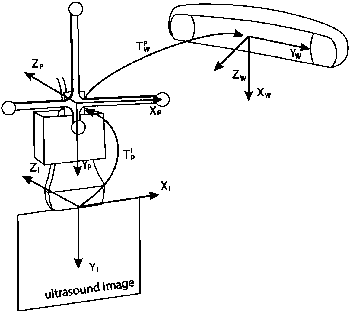
[0041] refer to figure 1 , The ultrasonic probe calibration device based on optical positioning of the present invention is composed of a visual tracking device (1), an ultrasonic acquisition device (2), a calibration device (3), and a computer (4).

[0042] refer to figure 1 , the ultrasonic probe (22) of the ultrasonic device (2) is fixed with a mark Mark1' that can be recognized by the visual tracking device (1).

[0043] refer to Figure 4 , the standardizer (3) is a water tank with a plurality of prisms with different heights at the bottom, and a mark Marker2 that can be recognized by the visual tracking device (1) on one side.

[0044] The computer (4) can collect ultrasound images scanned by the ultrasound equipment (2) and coordinates of Marker1 and Marker2 acquired by the visual tracking equipment (1).

[0045] In this implementation exampl...


PUM


Abstract

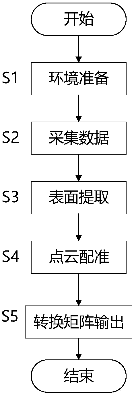
The invention relates to the field of medicine, and in particular relates to an ultrasonic probe calibration device and an ultrasonic probe calibration method based on optical positioning. The ultrasonic probe calibration device based on optical positioning is composed of a visual tracking device, an ultrasonic collecting device, a calibrator and a computer, wherein a tracking identification Marker 1 is fixed on an ultrasonic probe; the calibrator is a water tank with a plurality of trustums of different heights on the bottom, and one side of the calibrator is provided with a tracking identification Marker 2. An ultrasonic probe calibration method based on optical positioning comprises the following steps: segmenting a calibrator ultrasonic image collected by the ultrasonic probe, extracting the bottom picture contour of the calibrator, synchronously acquiring the coordinates of the Marker 1 and Marker 2 and the related position relation according to the visual tracking device, establishing the spatial position relation between the ultrasonic image and visual sense, and carrying out point cloud registration by adopting a coincidence point shift algorithm, and thus the coordinate transformation from the ultrasonic image pixel points to the three-dimensional space is realized. With the device and the method, the transformation precision from two-dimensional ultrasonic image information to three-dimensional space can be improved, and a basis is provided for the surgical navigation system based on the ultrasonic image.

Description

technical field [0001] The invention relates to the medical field, in particular to an optical positioning-based ultrasonic probe calibration device and method. Background technique [0002] Compared with CT and MRI images, ultrasound images have the advantages of short acquisition time, no ionizing radiation, economic convenience, real-time imaging, etc., and become an indispensable clinical diagnosis and treatment method. However, if one wants to understand the structure of the lesion more accurately, the traditional two-dimensional ultrasound cannot well meet the clinical requirements. Because the traditional B-mode ultrasound imaging system can only provide two-dimensional images of human body sections, clinicians can only reconstruct the three-dimensional structure of lesions in the brain based on experience, which requires high experience and skills of doctors. The impact is greater, and different doctors may have different surgical effects. It is also not conducive ...

Claims


Application Information

Patent Timeline
IPC IPC(8): A61B8/00
CPCA61B8/483A61B8/5215
Inventor 王利峰王田苗胡磊郭娜刘洪澎韩仲浩杨标
Owner BEIHANG UNIV
Learn More