Pin pressing device

A pin pressing and riveting technology, applied in the direction of feeding devices, positioning devices, storage devices, etc., can solve problems such as low efficiency, safety, and hidden dangers

Pending Publication Date: 2018-02-23
惠州市创欣隆五金制品有限公司
View PDF0 Cites 5 Cited by
  • Summary
  • Abstract
  • Description
  • Claims
  • Application Information

AI Technical Summary

Problems solved by technology

The latter is usually achieved by a riveting press. During the operation, it is necessary to manually put the heat sink into the riveting press, and then manually take it out after the riveting is pressed into the pin, and then continue the cycle operation. This processing method is inefficient and has Security risks

Method used


Image

  • Pin pressing device
  • Pin pressing device
  • Pin pressing device

Examples


Embodiment Construction

[0023] It should be noted that, in the case of no conflict, the embodiments of the present invention and the features in the embodiments can be combined with each other. The technical solutions of the present invention will be further described below in conjunction with the accompanying drawings of the embodiments of the present invention, and the present invention is not limited to the following specific embodiments.

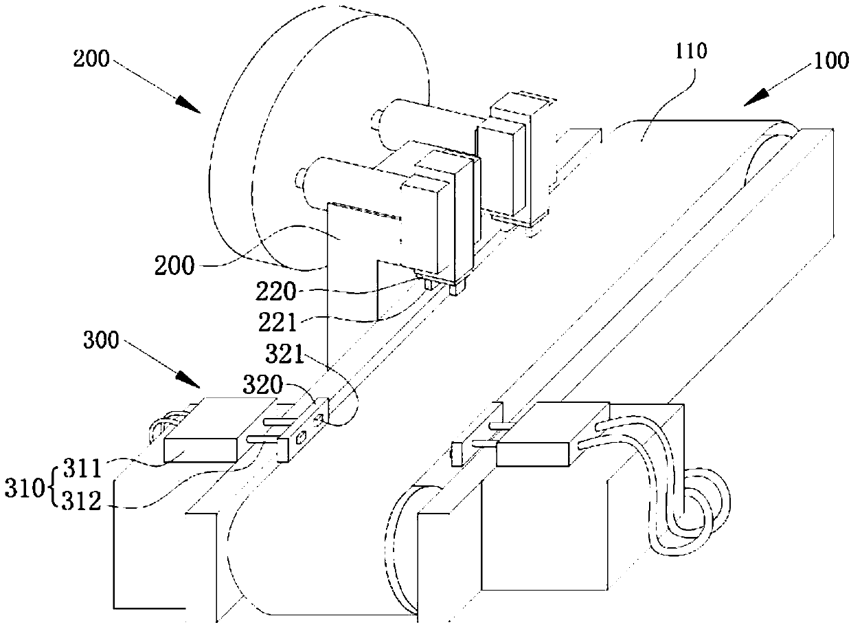
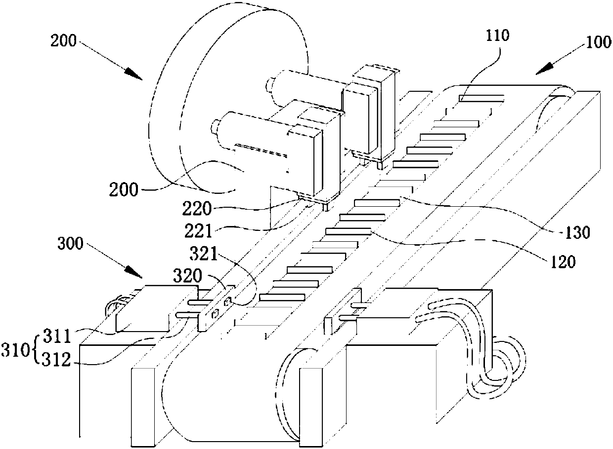
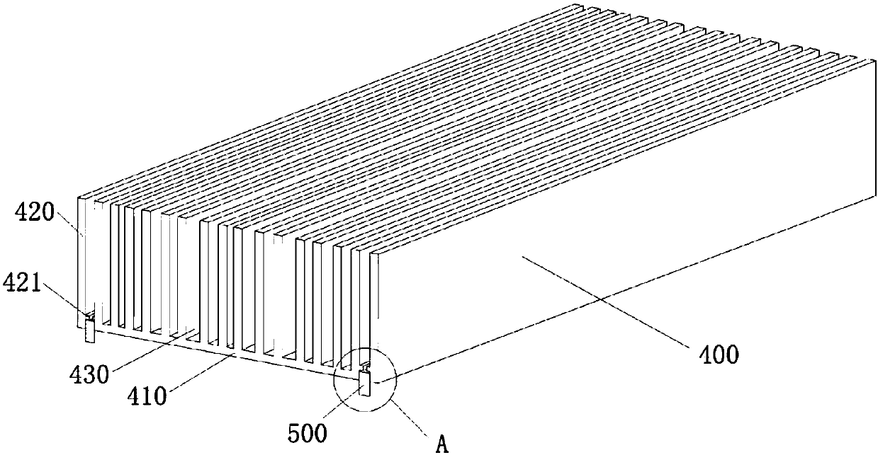
[0024] Such as figure 1 As shown, it is a pin pressing device of an embodiment, which is used to press the pin 500 on the heat sink body 400, including a transmission mechanism 100, a riveting mechanism 200 and a bending mechanism 300. The transmission mechanism 100 includes The conveyor belt 110, the riveting mechanism 200 includes a first cylinder 210 and two movable riveting heads 220, the first cylinder 210 is drivingly connected to the two riveting heads 220, and the two riveting heads 220 is disposed opposite to the conveyor belt 110, and the two rivetin...


PUM


Abstract

The invention relates to a pin pressing device, which includes a transmission mechanism, a riveting mechanism and a bending mechanism. The transmission mechanism includes a conveyor belt. The riveting mechanism includes a first cylinder and two movable riveting heads. The riveting head is driven and connected, the two riveting heads are arranged opposite to the conveyor belt, and the two riveting heads respectively protrude toward the conveyor belt to form at least two first pressing parts; the bending mechanism includes a second cylinder and two pressing parts, The number of the second cylinder is two, and each second cylinder is fixedly connected with a press-fit part respectively, and each second cylinder includes a second cylinder body and a piston rod, and a press-fit part is fixedly connected with a piston rod, two The pressing parts are arranged oppositely, and are respectively arranged on two sides of the conveyor belt. Each pressing part protrudes toward the conveyor belt to form at least two second pressing parts. Through the automatic feeding of the conveyor belt, the pins are pressed on the heat sink by the riveting mechanism and the bending mechanism, which realizes the automatic processing of the pins into the heat sink, and improves the efficiency and safety.

Description

technical field [0001] The invention relates to a pin pressing device in the heat sink manufacturing industry. Background technique [0002] Heat sink is a device for dissipating heat from electronic components that are prone to heat in electrical appliances. It is mostly made of aluminum alloy, brass or bronze into plates, sheets, and multi-sheets. As we all know, many electronic products and equipment generate heat during use, and the operating temperature of electronic equipment has a great impact on its service life and stability, so heat sinks are often required for use. In order to solder the heat sink to the circuit board of the electronic device, pins are provided on both sides of the heat sink. The pins and the heat sink have a separate structure, so the pins need to be inserted into the grooves of the heat sink by external force. At present, many pins are manually inserted into the slots of the heat sink, or the pins are inserted using pressure. The latter is usu...

Claims


Application Information

Patent Timeline
Patent Type & Authority Applications(China)
IPC IPC(8): B21D39/00B21D43/00B21D43/12B21D53/02B21C51/00
CPCB21D39/00B21C51/00B21D43/003B21D43/12B21D53/02
Inventor 郑运齐
Owner 惠州市创欣隆五金制品有限公司
Why Eureka
Try Eureka