Multifunctional screw turning device

A multi-functional screw-screwing technology, applied in the field of multi-functional screw-screwing devices, can solve problems such as hidden dangers of component safety, low processing efficiency, unreliable component fixing, etc., and achieve the effect of improving efficiency and saving energy.

Inactive Publication Date: 2018-02-23
嘉善县晓海金属制品厂(普通合伙)
9 Cites 16 Cited by

AI-Extracted Technical Summary

Problems solved by technology

The traditional way is to work with a hand-held screwdriver for screwing operations. The labor intensity of workers is high and the quality of screwing cannot be guaranteed. There are also electric screwing machines for operations, but the existing screwing machines can only handle one screw. When working on many parts, it is often necessary to fix two rows of parallel screws on the parts, which requires a screw machine to screw each screw one by one. At the same time, it is necessary to continuously adjust the posit...

Abstract

The invention discloses a multifunctional screw turning device. The multifunctional screw turning device comprises a worktable, a turning mechanism, a positioning mechanism and a control mechanism. The turning mechanism comprises a lifting fixing plate, a turning motor and a driving box; a driving bevel gear and two driven bevel gears are arranged in the driving box; the turning motor drives the driving bevel gear to rotate so as to drive the driven bevel gears; the bottoms of the driven bevel gears are fixedly connected with driven shafts; and the bottoms of the driven shafts are detachably connected with turning heads. A lifting mechanism comprises guide columns, a lifting lead screw and sliding sleeves arranged on the guide columns in a sleeving mode, and a lifting nut in engaged transmission with the lifting lead screw is arranged on the lifting lead screw in a sleeving mode and fixedly connected with the sliding sleeve on the guide column on the left side. The positioning mechanism comprises a positioning base, lifting sleeves, a horizontal sliding rail and a sliding bottom block. The multifunctional screw turning device can conduct turning operation on two screws simultaneously, parts are fixed reliably, the screw turning efficiency is high, and the screw turning quality is good.

Application Domain

Technology Topic

Image

  • Multifunctional screw turning device
  • Multifunctional screw turning device
  • Multifunctional screw turning device

Examples

  • Experimental program(1)

Example Embodiment

[0023] In order to make the technical means, creative features, objectives and effects of the present invention easy to understand, the present invention will be further explained below in conjunction with specific embodiments.
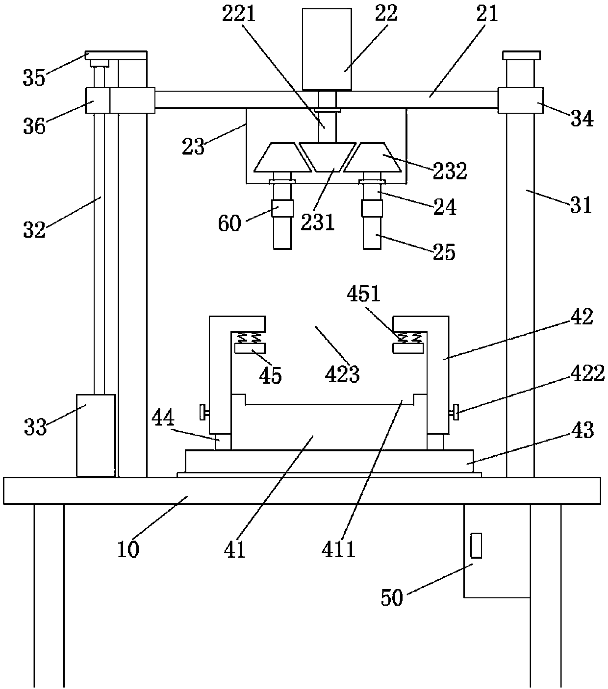
[0024] See Figure 1 ~ Figure 4 , The multifunctional screwing device of the present invention includes a worktable 10, a tightening mechanism, a positioning mechanism, a lifting mechanism and a control mechanism.
[0025] The tightening mechanism includes a fixing plate 21, a tightening motor 22 and a driving box 23. The fixing plate 21 is transversely arranged above the workbench 10, and the tightening motor 22 and the driving box 23 are respectively fixed on the upper and lower parts of the fixing plate 21. The driving box 23 is provided with a driving bevel gear 231 and two driven bevel gears 232. The fixing plate 21 is provided with a first through hole, and the output shaft 221 of the screwing motor 22 passes through the first through hole and is fixed to the driving bevel gear 231. The two driven bevel gears 232 are symmetrically arranged on both sides of the driving bevel gear 231 and both mesh with the driving bevel gear 231 for transmission. The bottom of the driven bevel gear 232 is fixedly connected with the driven shaft 24, and the bottom of the driving box 23 is provided with two second through holes. A rotating bearing is installed in the second through hole, and the driven shaft 24 passes through the rotating bearing and is rotatably erected in the driving box 23 through the rotating bearing. When in use, the driving bevel gear 231 is driven to rotate by tightening the motor 22, thereby driving the two driven bevel gears 232 to rotate, and the rotation of the driven bevel gear 232 can drive the tightening head 25 to rotate through the driven shaft 24 to perform the screwing operation.
[0026] A tightening head 25 is detachably connected to the bottom of each driven shaft 24. The bottom of the tightening head 25 is a cross-shaped or flat-head screwdriver. It can also be an Allen wrench or other structure for screwing bolts. The tightening head 25 can be replaced with a different structure according to actual usage requirements. Two side-by-side bolts can be tightened or loosened simultaneously by the two tightening heads 25. When only one bolt needs to be operated, only one of the tightening heads 25 needs to be removed.
[0027] The lifting mechanism includes a guide column 31, a lifting screw 23 and a lifting motor 33 for driving the lifting screw 23 to rotate. There are two guide posts 31 and they are respectively installed on the workbench 10 on the left and right sides of the fixing plate 21. A sliding sleeve 34 is sleeved on the guide post 31, and two ends of the fixing plate 21 are respectively fixedly connected with the sliding sleeves 34 on both sides. The lifting screw 23 is vertically arranged on one side of the guide column 31 on the left side, the lifting motor 33 is fixed on the workbench 10, and the output end of the lifting motor 33 is fixed to the bottom of the lifting screw 23. An end plate 35 is installed on the top of the guide column 31 on the left side, a frame block is installed on the bottom of the end plate 35, and the top of the lifting screw 23 is rotatably erected on the end plate 35 through the frame block. The lifting screw 23 is sheathed with a lifting screw nut 36 engaged with it for transmission, and the lifting screw 36 is fixedly connected with the sliding sleeve 34 on the left guide column 31. When in use, the lifting motor 33 drives the lifting screw 23 to rotate, thereby driving the lifting screw nut 36 to move up and down in the extension direction of the lifting screw 23, thereby driving the sliding sleeve 34 to slide up and down along the height direction of the guide column 31 to drive Lifting of the fixed plate 21.
[0028] The positioning mechanism is arranged under the fixed plate 21, and the positioning mechanism includes a positioning base 41, a lifting sleeve 42, a horizontal slide rail and a sliding bottom block 43. The horizontal smoothing rail is installed on the workbench 10, the sliding bottom block 43 is arranged on the horizontal sliding rail to be horizontally movable back and forth along the extending direction of the horizontal sliding rail, and the positioning base 41 is installed on the sliding bottom block 43. The lifting sleeve 42 has an n-shaped structure. The sliding bottom blocks 43 on both sides of the positioning base 41 are symmetrically installed with an adjusting plate 44, and the adjusting plate 44 is provided with threaded holes. The bottom of the side ears on both sides of the lifting sleeve 42 are respectively provided with a strip-shaped notch 421, and a locking bolt 422 is penetrated in the strip-shaped notch 421. The external thread of the locking bolt 422 is matched with the internal thread of the threaded hole. The top of the lifting sleeve 42 is provided with a processing opening 423, and a rubber compression ring 45 is provided below the processing opening 423. The top of the rubber compression ring 45 is connected to the bottom surface of the top of the lifting sleeve 42 through a compression spring 451. When in use, the component to be screwed is placed in the recess 411 of the positioning base 41, the thickness direction of the component is limited by the lifting sleeve 42, and the locking bolt 422 is connected with the strip notch 421 and the threaded hole. The lifting sleeve 42 is fixed in cooperation; the rubber compression ring 45 is used to reliably compress the components and prevent their vibration.
[0029] The control mechanism includes a control box 50, which is fixed at the bottom of the workbench 10, and a PLC controller is installed in the control box 50. The PLC controller is electrically connected to the lifting motor 33 and the tightening motor 22 respectively.
[0030] The driven shaft 24 is connected to the tightening head 25 through a mounting assembly 60, and the mounting assembly 60 includes an insert 63. The bottom of the driven shaft 24 is fixedly connected with a rectangular insert block 61, and the top of the screwing head 25 is provided with a slot 62 corresponding to the insert block 61. The insert block 61 and the tightening head 25 are respectively provided with a first through hole and a second through hole in the horizontal direction, and the insert bar 63 is inserted in the first through hole and the second through hole.
[0031] The installation assembly further includes a limit ring 64 which is sleeved on the driven shaft 24. The inner wall of the stop ring 64 near the top is provided with an internal thread, and the outer wall of the driven shaft 24 near the bottom is provided with an external thread that matches the inner thread of the stop ring 64. When replacing a different tightening head 25, insert the insert block 61 into the slot 62 of the tightening head 25, and pass the insert 63 through the first through hole and the second through hole in turn, so that the tightening head 25 and the slave The moving shaft 24 is quickly connected. During the operation, a circumferential force is generated between the tightening head 25 and the driven shaft 24. Since the inserting strip 63 is inserted laterally, the two will not be relatively loose during operation. The limit ring 64 is sleeved on the driven shaft 24. After the insert 63 is inserted, the limit ring 64 is rotated to move the limit ring 64 downward, so that the side wall of the limit ring 64 is sleeved on the driven shaft 24 and the tightening head 25, so that the stop ring 64 covers the first through hole and the second through hole, so as to prevent the insert 63 from falling out of the first through hole and the second through hole, so that the driven The connection between the shaft 24 and the tightening head 25 is not only fast and convenient, but also reliable.
[0032] A storage groove 411 is opened on the positioning base 41.
[0033] The holding groove 411 has a rectangular structure, and a plurality of zigzag-shaped anti-slip protrusions 71 are uniformly installed along the length direction of the holding groove 411, and the anti-slip protrusions 71 are made of rubber. The length of the anti-slip protruding strip 71 is adapted to the width of the storage groove 411. The two sides of the holding groove 411 are also provided with fixing components symmetrically, and the fixing components include an abutment plate 72 and a threaded rod 73. Perforations are formed on both sides of the holding groove 411, and the threaded rod 73 penetrates through the perforations. One end of the threaded rod 73 is fixedly connected with the abutment plate 72, the other end of the threaded rod 73 extends out of the positioning base 41, and a locking nut 74 is sleeved on the extending end. The component is preliminarily positioned through the storage groove 411, the side plate of the component is pressed against and pressed by the abutment plate 72, and fixed by rotating the locking nut 74, so that the component can be positioned in the width direction of the storage groove 411 Fixed; The non-slip protruding strip 71 can effectively prevent the component from shifting in the holding groove 411, especially extending the length of the holding groove 411.
[0034] The basic principles and main features and advantages of the present invention have been shown and described above. Those skilled in the industry should understand that the present invention is not limited by the foregoing embodiments. The foregoing embodiments and descriptions only illustrate the principles of the present invention. Without departing from the spirit and scope of the present invention, the present invention may have Various changes and improvements, these changes and improvements fall within the scope of the claimed invention. The scope of protection claimed by the present invention is defined by the appended claims and their equivalents.

PUM

no PUM

Description & Claims & Application Information

We can also present the details of the Description, Claims and Application information to help users get a comprehensive understanding of the technical details of the patent, such as background art, summary of invention, brief description of drawings, description of embodiments, and other original content. On the other hand, users can also determine the specific scope of protection of the technology through the list of claims; as well as understand the changes in the life cycle of the technology with the presentation of the patent timeline. Login to view more.

Similar technology patents

Classification and recommendation of technical efficacy words

  • Improve efficiency
  • Energy saving
Why Eureka
Try Eureka