Intelligent injection molding forming equipment

An injection molding and intelligent technology, applied in the field of intelligent injection molding equipment, can solve problems such as waste and energy loss, and achieve the effects of reducing energy consumption, reducing energy loss, and reducing production costs

Inactive Publication Date: 2018-02-23
XIAMEN TUBETECH INC
View PDF7 Cites 4 Cited by
  • Summary
  • Abstract
  • Description
  • Claims
  • Application Information

AI Technical Summary

Problems solved by technology

For a single molding cycle, the plasticizing system is only effective in the two processes of "glue injection and pressure holding", and is in a standby state during the other four processes. During the standby process, the heating in the plasticizing system The unit is always in working condition, causing additional loss of energy
On an all-electric injection molding machine, this energy loss is a major source of waste

Method used


Image

  • Intelligent injection molding forming equipment

Examples


Embodiment 1

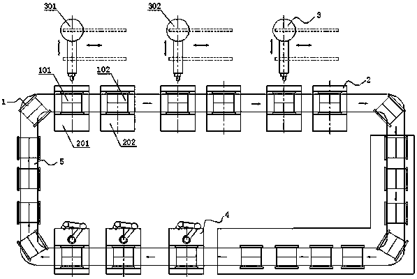
[0031] Such as figure 1 As shown, the present invention provides an intelligent injection molding equipment. The injection molding system includes several mold components 1, several high-pressure mold clamping units 2, several mobile injection molding units 3, several retrieving units 4, intelligent conveying And positioning unit 5 and control unit;

[0032] The mold assembly 1 includes a mold and a low-pressure mold clamping mechanism, and the low-pressure mold clamping mechanism can lock the mold when transporting the mold; the control unit can call the corresponding process of the mold for injection molding; the high-pressure clamping mechanism can The mold unit 2 can lock the mold assembly 1 according to the corresponding mold clamping process requirements; the mobile injection unit 3 can inject glue into the mold assembly 1 according to the corresponding injection molding process requirements; the material taking unit 4 can open the mold and take out the molded plastic p...

Embodiment 2

[0052] combine figure 1 , the present invention provides an intelligent injection molding equipment, the injection molding system includes a number of mold components 1, a number of high-pressure mold clamping units 2, a number of mobile injection molding units 3, a number of retrieving units 4, intelligent conveying and positioning unit 5 and control unit;

[0053] The mold assembly 1 includes a mold and a low-pressure mold clamping mechanism, and the low-pressure mold clamping mechanism can lock the mold when transporting the mold; the control unit can call the corresponding process of the mold for injection molding; the high-pressure clamping mechanism can The mold unit 2 can lock the mold assembly 1 according to the corresponding mold clamping process requirements; the mobile injection unit 3 can inject glue into the mold assembly 1 according to the corresponding injection molding process requirements; the material taking unit 4 can open the mold and take out the molded p...


PUM


Abstract

The invention discloses an intelligent injection molding forming equipment. An injection molding forming system comprises a plurality of die assemblies, a plurality of high-pressure die assembling units, a plurality of movable injection molding units, a plurality of material taking units, an intelligent conveying and positioning unit and a control unit. Each die assembly comprises a die and a low-pressure die locking mechanism, wherein the low-pressure die locking mechanism can lock the die during die conveying, and the control unit can call the corresponding technology of the die for injection molding forming. The high-pressure die assembling units can tightly lock the die assemblies according to the corresponding die assembling technology requirements. The movable injection molding unitscan conduct glue shooting to the interiors of the die assemblies according to the corresponding injection molding technology requirement. The material taking units can conduct die sinking and take out formed plastic parts. The intelligent conveying and positioning unit can convey and position the die assemblies. By adoption of the intelligent injection molding forming equipment, small-batch customized forming production can be achieved, equipment energy consumption is reduced, and the equipment efficiency is improved.

Description

technical field [0001] The invention relates to injection molding equipment, in particular to an intelligent injection molding equipment. Background technique [0002] In traditional injection molding equipment, the plasticizing unit, clamping mechanism, frame and control unit are all in one-to-one correspondence and work in a fixed combination. The mold is firmly locked on the fixed platen of the injection molding machine, and the entire molding process is completed on the injection molding machine. There is a relatively fixed relationship between the mold and the injection molding machine, and the production mode is mostly the same batch of mass production, so it cannot meet the needs of small batches of customized production of different batches in the future. [0003] Under normal circumstances, a complete injection molding cycle can be roughly disassembled into six processes including "mold closing, injection, pressure holding, cooling, mold opening, and material remov...

Claims


Application Information

Patent Timeline
Patent Type & Authority Applications(China)
IPC IPC(8): B29C45/03B29C45/17B29C45/76
CPCB29C45/03B29C45/17B29C45/76B29C2945/76993
Inventor 郑加茹
Owner XIAMEN TUBETECH INC
Why Eureka
Try Eureka