A three-phase electrostatic coalescence separator for oil, gas and water

An electrostatic coalescence and separator technology, applied in the field of multiphase separation of oil and gas gathering and transportation systems, can solve the problems of no water layer monitoring system, increased risk, and easy electrode breakdown, etc. Breakdown problems, effects that increase the chance of collision

Active Publication Date: 2019-11-15
CHINA UNIV OF PETROLEUM (EAST CHINA)
View PDF2 Cites 1 Cited by
  • Summary
  • Abstract
  • Description
  • Claims
  • Application Information

AI Technical Summary

Problems solved by technology

However, this device only considers the dielectrophoresis phenomenon in the process of electrostatic coalescence in the first chamber, the effect of electrostatic coalescence in the second chamber cannot be guaranteed, and there is no accurate water layer monitoring system, the safety of the bare metal electrodes in the second chamber The safety cannot be guaranteed, and the transformer is externally installed, and the high-voltage circuit increases the risk
[0005] In summary, in view of the problems of low separation efficiency, easy breakdown of electrodes, and inability to effectively deal with high emulsification and high water content crude oil emulsions in the traditional three-phase separation process, it is necessary to invent a method for breaking high emulsification and high water content crude oil emulsions. The milk treatment effect is remarkable, and it is suitable for the oil-gas-water three-phase separation device of the produced fluid of land and offshore oilfields

Method used


Image

  • A three-phase electrostatic coalescence separator for oil, gas and water
  • A three-phase electrostatic coalescence separator for oil, gas and water
  • A three-phase electrostatic coalescence separator for oil, gas and water

Examples


Embodiment Construction

[0039] The present invention will be further described below in conjunction with the accompanying drawings and embodiments.

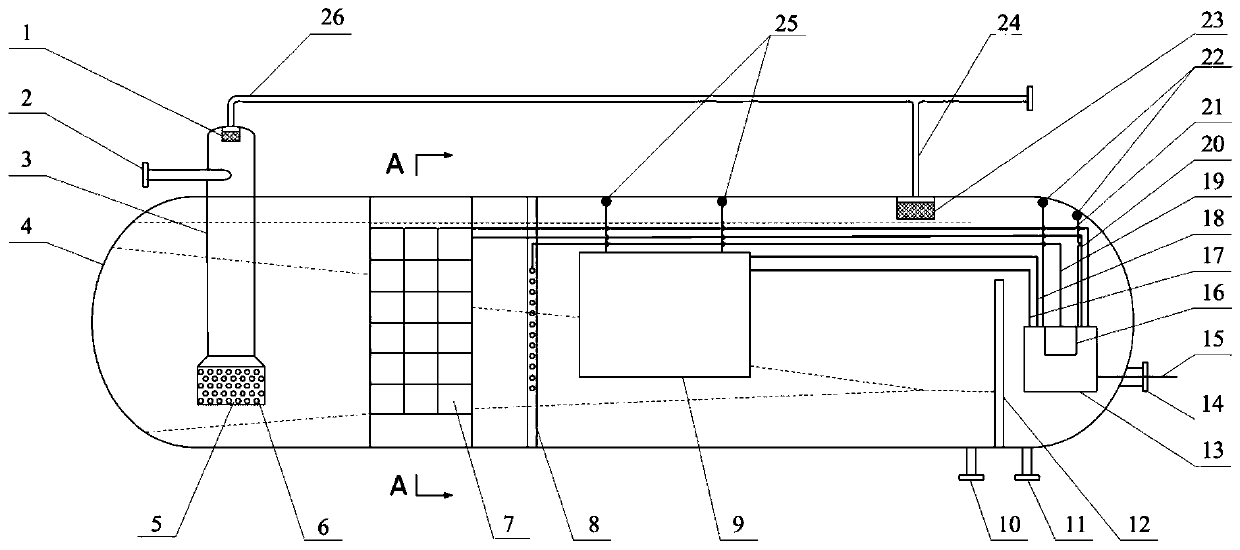
[0040] Such as figure 1 As shown, an oil-gas-water three-phase electrostatic coalescence separator, including a separator main body, a gas-liquid separation module, a high water content coalescence module, a low water content coalescence module, a power supply and a control system;

[0041] The main body of the separator includes a horizontal cylinder 4, a weir plate 12 is vertically arranged on the right side of the horizontal cylinder 4, and a water outlet 10 is arranged at the bottom of the horizontal cylinder 4 on the left side of the weir plate 12. The bottom of the horizontal cylinder 4 on the right side of the plate 12 is provided with an oil outlet 11; the right end of the horizontal cylinder 4 is provided with a cable lead hole 14;

[0042] The gas-liquid separation module is vertically inserted into the left side of the horizontal cylinder 4,...


PUM


Abstract

The invention discloses an oil-gas-water three-phase electrostatic coalescence separator, which comprises a separator main body, a gas-liquid separation module, a high-water coalescence module, a low-water coalescence module, a power supply and a control system; a gas-liquid separation module, a high water The coalescing module, low water content coalescing module, power supply and control system are located inside the main body of the separator; the gas-liquid separation module is vertically inserted into the left side of the horizontal cylinder, and the high water content coalescence module is located on the right side of the gas separation module; the low water content coalescence The junction module is located on the right side of the high water content coalescing module, and the power supply and control system is located on the right side of the weir plate. The oil, gas and water three-phase electrostatic coalescence separator of the present invention realizes the four-stage separation design of oil, gas and water through the gas-liquid separation module, the high water content coalescence module, the low water content coalescence module and the gravity sedimentation module in the horizontal cylinder body, which greatly simplifies the design on the one hand Separation technology realizes intensive separation; on the other hand, it can handle oil-water emulsions with a wide range of water content and significantly improve the separation effect.

Description

technical field [0001] The invention belongs to the technical field of multiphase separation of oil and gas gathering and transportation systems, and in particular relates to an oil, gas, and water three-phase electrostatic coalescence separator, which is suitable for the oil, gas, and water separation process of oil, gas, and water produced in land and offshore oil fields, and realizes gas-liquid separation and oil-water demulsification , has the advantages of compact structure, wide application range, high separation efficiency and full energy utilization. Background technique [0002] At present, most oil fields in my country mainly use the combination of gravity three-phase separator and electric dehydrator for gas-liquid separation and crude oil demulsification. However, as the oilfield gradually enters the middle and late stages of development, the water content of the produced fluid increases sharply. At the same time, the wide application of tertiary oil recovery tec...

Claims


Application Information

Patent Timeline
Patent Type & Authority Patents(China)
IPC IPC(8): B01D19/00B01D17/02B01D17/06B01D17/025C10G33/02
CPCB01D17/0208B01D17/045B01D17/06B01D19/0057C10G33/02
Inventor 罗小明黄鑫任静何利民吕宇玲杨东海
Owner CHINA UNIV OF PETROLEUM (EAST CHINA)
Why Eureka
Try Eureka