Top-reduced oil-water separation tank

A technology for oil-water separation tanks and cylinders, which is applied in the directions of refining by centrifugal force, dehydration/demulsification by electricity/magnetism, dehydration/demulsification by mechanical methods, etc. It can solve the problems of low oil-water separation efficiency, uncombined use of electrostatic coalescence, Difficult to completely separate and other problems, to achieve the effect of improving oil-water separation efficiency, shortening hydraulic retention time, and simplifying the separation process

Pending Publication Date: 2022-05-03
CHINA PETROLEUM & CHEM CORP +2
View PDF5 Cites 0 Cited by
  • Summary
  • Abstract
  • Description
  • Claims
  • Application Information

AI Technical Summary

Problems solved by technology

But the disadvantage is: only through the separation channel coated with hydrophobic membrane and the liquid level floating plate for physical separation, without combining the technical advantages of electrostatic coalescence separation and cyclone separation, the scope of application is narrow
However, the disadvantages are: oil-water separation is only performed through multi-stage electrostatic coalescence, without combining the technical advantages of gravity sedimentation and cyclone separation, and in addition, it does not consider the associated gas carried by equipment such as plate heat exchangers and electric desalination tanks in the pre-process process The removal, the scope of application is narrow
[0005] As mentioned above, the internal structure of the existing top-reduced oil-water separation tank is not effective in removing oil from highly emulsified crude oil, and at the top of the decompression tower, the flow rate of oil and water is very fast, and the boundary position is blurred and it is difficult to completely separate, which is easy to cause degreasing. The loss of top oil, in addition, the oil-water separation efficiency is low, and the mixed medium enters the subsequent process flow, which brings certain safety hazards to the sour water stripping unit and hydrogenation unit

Method used


Image

  • Top-reduced oil-water separation tank
  • Top-reduced oil-water separation tank
  • Top-reduced oil-water separation tank

Examples


Embodiment Construction

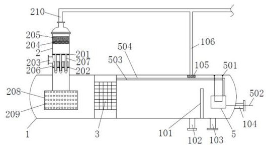
[0030] Such as figure 1 As shown, a roof-reducing oil-water separation tank of the present invention includes a horizontal cylinder 1, a vertical cylinder 2, an electrostatic coalescence unit 3 and a transformer 5, and the right side of the horizontal cylinder 1 is opposite to the horizontal cylinder. A weir plate 101 is vertically provided at the bottom of the body 1, a water outlet 102 is provided at the bottom of the horizontal cylinder 1 on the left side of the weir plate 101, an oil outlet 103 is provided at the bottom of the horizontal cylinder 1 on the right side of the weir plate 101, and the vertical The cylinder body 2 is vertically inserted into the left side of the horizontal cylinder body 1, the electrostatic coalescence unit 3 is located inside the horizontal cylinder body 1 between the vertical cylinder body 2 and the weir plate 101, and the electrostatic coalescence unit 3 and the transformer 5 The two are electrically connected through a high-voltage cable 503...


PUM


Abstract

The invention discloses a top-reduced oil-water separation tank which comprises a horizontal cylinder, a vertical cylinder, an electrostatic coalescence unit and a transformer, a weir plate is vertically arranged on the right side in the horizontal cylinder, the vertical cylinder is vertically inserted into the left side of the horizontal cylinder, and the electrostatic coalescence unit is located in the horizontal cylinder between the vertical cylinder and the weir plate. The electrostatic coalescence unit comprises a plurality of corrugated electrode plates arranged in parallel in the front-back direction, a flow channel is formed between every two adjacent corrugated electrode plates, a liquid distribution component is arranged at the bottom of the vertical cylinder, an upper tube plate and a lower tube plate are sequentially and horizontally arranged in the vertical cylinder from top to bottom, and a cyclone tube is vertically and fixedly arranged on the lower tube plate. A rotational flow exhaust pipe is arranged at the top of the rotational flow pipe. Three-stage separation of oil, gas and water can be realized, the separation process is greatly simplified, and intensive separation is realized.

Description

technical field [0001] The invention relates to the technical field of a vacuum tower system of an atmospheric and vacuum device in the oil refining industry, in particular to a top-reducing oil-water separation tank. Background technique [0002] As oilfield exploitation gradually enters the middle and late stages, the water content of crude oil increases sharply. At the same time, the wide application of tertiary oil recovery technologies such as chemical flooding intensifies the emulsification of crude oil. The emulsification of various equipment at the top of the pressure tower is serious. At present, the top-reducing oil-water separation tank in the refinery mainly absorbs the top-reducing oil from each evacuated condenser, as well as part of the top-reducing gas and sulfur-containing sewage, and separates oil, gas, and water into three phases, and discharges them to the top-reducing oil pump respectively. , roof-reducing drainage pump and non-condensable gas skid-moun...

Claims


Application Information

Patent Timeline
Patent Type & Authority Applications(China)
IPC IPC(8): C10G33/02C10G33/06C10G31/10
CPCC10G33/02C10G33/06C10G31/10
Inventor 梁文凯
Owner CHINA PETROLEUM & CHEM CORP
Why Eureka
Try Eureka