

Novel nozzle rotational flow structure and nozzle structure
A new type of spiral technology, applied in the field of coal gasification, can solve the problem that the DC impingement pulverized coal burner cannot meet various process requirements, achieve good atomization effect and improve economic benefits
Inactive Publication Date: 2018-02-23
陕西宏远流体控制设备有限公司
View PDF0 Cites 1 Cited by
- Summary
- Abstract
- Description
- Claims
- Application Information
AI Technical Summary
Problems solved by technology
The DC impingement type has the advantages of simple processing and manufacturing, so it is widely used in the field of burners (burners). However, with the continuous emergence of various coal chemical processes in recent years, the DC impact pulverized coal burner can no longer meet various Process requirements
Method used
View moreImage
Smart ImageViewing Examples

Examples
Embodiment Construction
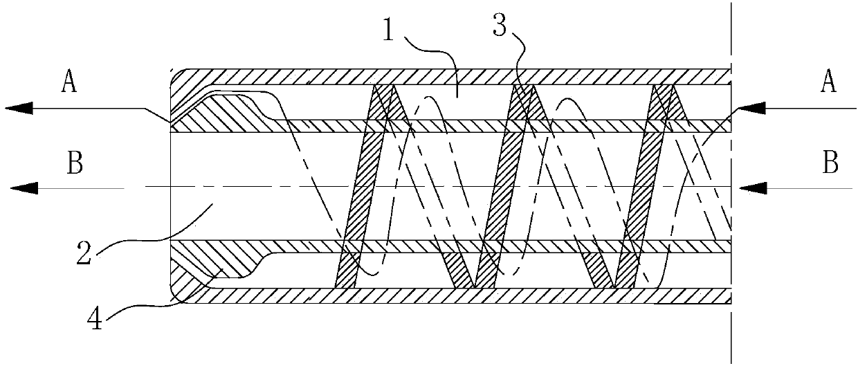
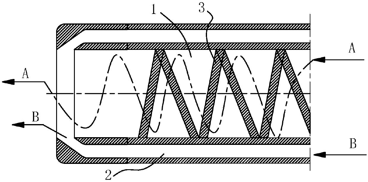
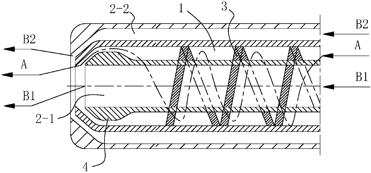
[0021] The present invention is described in further detail below in conjunction with accompanying drawing:
[0022] see Figure 1-Figure 3 , the present invention first proposes a novel burner swirl structure, which is specifically: a spiral partition 3 capable of rotating and flowing the combustion medium A is provided on the inner wall of the combustion medium passage 1 in the burner, because the combustion medium A It has a strong wear and corrosion effect on the partition, so the spiral partition 3 is a wear-resistant and corrosion-resistant spiral strip plate.
Login to View More PUM
 Abstract
The invention discloses a novel nozzle rotational flow structure and a nozzle structure. The novel nozzle rotational flow structure is characterized in that a spiral baffle plate which is capable of enabling combustible medium to rotationally flow is arranged on the inner wall of a combustible medium passage formed in a nozzle, and the spiral baffle plate is an anti-wear and anti-corrosion spiralstripped plate; the spiral baffle plate stretches towards a direction of a spray head of the nozzle. Compared with a direct flow impact type structure in the prior art, a spiral linear structure of the invention has the advantages that the atomization effect is better, the technological requirements of various coal chemistry industry technologies can be met, and the economic benefit of a coal chemical industry enterprise is effectively increased.
Description
technical field [0001] The invention belongs to the technical field of coal gasification, and relates to burner technology, in particular to a novel burner swirl structure and burner structure. Background technique [0002] Coal chemical industry refers to the process of using coal as raw material to convert the effective components in coal into gas, liquid or solid fuels and related chemicals through a series of devices and chemical processes. Coal gasification is one of the key technologies in the coal chemical industry, and pulverized coal burners are the core of coal gasification technology. [0003] There are two main forms of pulverized coal burner combustion in coal chemical industry: one is to process coal into powder, accompanied by a certain proportion of "fluidizing" gas (such as CO 2 or N 2 etc.), through the pulverized coal burner at a certain speed and direction into the combustion chamber (hearth) for combustion, it is a gas-solid two-phase medium. The seco...
Claims
Login to View More Application Information
Patent Timeline
 Patent Type & AuthorityApplications(China)
IPC IPC(8): C10J3/48C10J3/50
CPCC10J3/48C10J3/50C10J2200/152C10J2300/093C10J2300/0959
Inventor韩晋平刘保荣廖红春
Owner陕西宏远流体控制设备有限公司