Device and method for evaluating capillary force in water injection process of oil reservoir

A capillary force and oil reservoir technology, which is applied in the direction of earthwork drilling, fluid extraction, and undisturbed core extraction devices, can solve problems such as limited measurement range, testing capillary force, and affecting fluid distribution in the core, and achieves the goal of weakening the liquid end effect Impact, error reduction, targeted effects

Inactive Publication Date: 2018-02-23
SOUTHWEST PETROLEUM UNIV
View PDF6 Cites 10 Cited by
  • Summary
  • Abstract
  • Description
  • Claims
  • Application Information

AI Technical Summary

Problems solved by technology

Mercury porosimetry has a fast test speed and a large measurement range, but it is quite different from the actual situation of the oil layer, pollutes the environment, and the core cannot be reused
Centrifugal test equipment and calculation are more complicated, the measurement range is limited, and the maximum pressure is only 1.4MPa
The semi-permeable barrier method is close to the conditions of the oil layer, and the measurement accuracy is high, but it will affect the fluid distribution in the core
When these methods are applied to determine the capillary force in the reservoir water injection process, there are several problems: (1) The fluid flow mode during the test process is different from the fluid flow mode under formation conditions, such as the most accurate semi-permeable diaphragm method One end enters the high-pressure fluid, and the other end seals the ...

Method used


Image

  • Device and method for evaluating capillary force in water injection process of oil reservoir
  • Device and method for evaluating capillary force in water injection process of oil reservoir
  • Device and method for evaluating capillary force in water injection process of oil reservoir

Examples


Embodiment Construction

[0018] The present invention will be described in further detail below in conjunction with the accompanying drawings and specific embodiments.

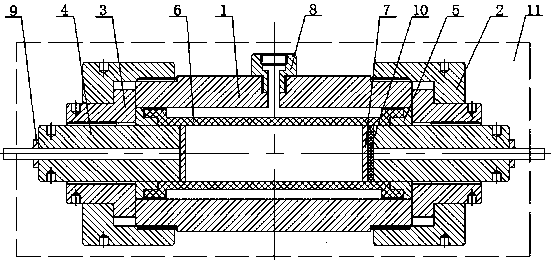
[0019] Such as figure 1 As shown, the core holder consists of a cylinder body 1, a sealing pressure cap 2, a plug 3, a core plug 4, a tapered sleeve 5, a rubber sleeve 6, a high-permeability metal partition 7, a ring pressure joint 8, and a pipeline fixing joint 9 , screen 10 and oven 11.

[0020] There is a rubber sleeve 6 inside the cylinder body 1, and the rock core to be tested can be placed in the rubber sleeve 6. The fixed ring pressure joint 8 is connected to the outside of the cylinder body 1, the central hole of the ring pressure joint 8 communicates with the inside of the cylinder body 1, the top of the ring pressure joint 8 can be connected to the pipeline, and the pipeline is connected to the confining pressure pump, and the core can be applied to the core through the confining pressure pump. Confining pressure.

[0021...


PUM


Abstract

The invention provides a device and method for evaluating the capillary force in water injection process of an oil reservoir. The device and the method can simulate the capillary force of a stratum inthe actual water injection process of the oil reservoir. A rubber sleeve is arranged in a cylinder of a core holder, the end of the rubber sleeve is sleeved with a tapered sleeve, a sealing press capis in threaded connection with the cylinder, and a stopper is fixed; the stopper is in threaded connection with a core plug, and the length of the core plug is adjusted; the inner end of the core plug is arranged in the rubber sleeve; a high-permeability metal isolation plate is arranged between the stopper and the core, and circulation channels are formed in the radius and tangential directionsof the high-permeability metal isolation plate; a sieve is arranged between the high-permeability metal isolation plate at the outlet end and the core plug, the outer end of the core plug is connectedwith a pipeline fixing connector, and an annular pressure connector is connected with the outer part of the cylinder. The method provides steps and processes for the specific operation of experimental equipment and how to obtain a curve about the capillary force and the saturation degree. The device and the method eliminate influences brought by semi-permeable isolation plates or semi-permeable membranes, meanwhile the influence of the liquid end effect is also weakened, and experimental data becomes more accurate and reliable.

Description

technical field [0001] The invention belongs to the technical field of laboratory experiments for oil and gas field development; in particular, it relates to a device and method for evaluating capillary force in the water injection process of oil reservoirs. Background technique [0002] Capillary force, or capillary pressure, refers to the additional pressure that exists on the curved interface of two immiscible fluids in the capillary. In the process of exploration and development of oil and gas fields, many properties of the reservoir, such as rock pore structure, rock storage performance, the relationship between oil-water saturation and the height of the oil-water transition zone, oil displacement efficiency, and wettability of reservoir rocks, etc. Determined using capillary force data. Therefore, accurate and effective acquisition of capillary force data is a prerequisite for oil and gas exploration and development. [0003] There are three main methods for measurin...

Claims


Application Information

Patent Timeline
IPC IPC(8): E21B49/00E21B47/007E21B43/20E21B25/00
CPCE21B25/00E21B43/20E21B47/007E21B49/00E21B49/008
Inventor 李海涛李斌斌李颖刘权崔小江
Owner SOUTHWEST PETROLEUM UNIV
Why Eureka
Try Eureka