Stator blade mounting structure

A technology for stator blades and mounting structures, which is applied to the supporting elements of blades, engine elements, machines/engines, etc., can solve the problems of high maintenance cost, difficult processing, and high cost of engines or gas turbines, and achieves a reduction in the self-excited vibration of the blades. Risks, reduce maintenance costs in the later period, and reduce the effect of processing costs

Active Publication Date: 2018-02-23
INST OF ENGINEERING THERMOPHYSICS - CHINESE ACAD OF SCI
View PDF4 Cites 12 Cited by
  • Summary
  • Abstract
  • Description
  • Claims
  • Application Information

AI Technical Summary

Problems solved by technology

It is not difficult to see that the stator casing assembly using the above processing method is very difficult to process and the cost is too high
In addition, during the operation of the engine or gas turbine, if there is a problem with one or several stator blades, the casing assembly where the entire stator blade is located will inevitably need to be overhauled or directly scrapped
This causes the maintenance cost of the engine or gas turbine to be too high, which is extremely unfavorable for improving the competitiveness of the engine
[0003] The existing integrated structure of the stator blade and the casing mainly has the difficulties of sealing the position of the type hole, the difficulty of disassembling and repairing the single blade or the difficulty in structural design, the difficulty of achieving precise positioning of the single blade in the assembly, and the difficulty of the stator blade when the air flow stimulates it. Under the action of vibration force, problems such as forced vibration are easy to occur, which seriously restricts the development of the engine

Method used


Image

  • Stator blade mounting structure

Examples


Embodiment Construction

[0026] In order to make the purpose, technical solutions and advantages of the present invention clearer, the present invention will be further described in detail below in conjunction with the examples. The following examples are explanations of the present invention and the present invention is not limited to the following examples.

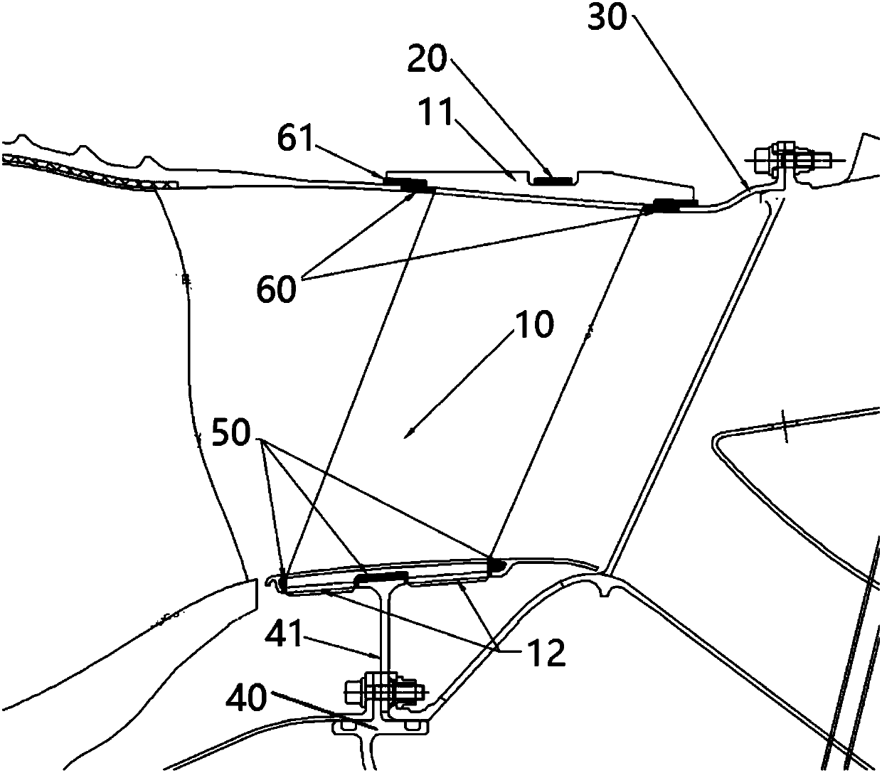
[0027] Such as figure 1 As shown, the stator vane installation structure of the present invention consists of an integrated stator vane 10 with a pressure plate 11, a blade outer ring clamp 20, an outer ring case 30 with a vane-shaped hole, an inner vane with a vane-shaped hole and a flange edge 41 The ring casing 40 , the inner ring light elastic member 50 and the outer ring light elastic member 60 are composed of parts, and a plurality of stator vanes 10 are arranged circumferentially between the inner ring casing 40 and the outer ring casing 30 .

[0028] The outer end of the stator blade 10 is integrally formed with a pressure plate structu...


PUM


Abstract

The invention relates to a stator blade mounting structure which can be applied to the fields of ground gas turbines, aero-engines and the like. The stator blade mounting structure comprises stator blades with a pressing plate, inner and outer ring light elastic parts, inner and outer ring casings and an outer ring pressing hoop. Through the parts, the single blade dismantling function of the stator blades can be achieved. As the light elastic parts are adopted, assembling and positioning of the whole-ring stator blades are achieved through the cold-state interference magnitude of the light elastic parts and the inner and outer ring blade profiles of the blades. Under an assembly state, the stator blade mounting structure has certain rigidity and can transfer aerodynamic torque of the stator blades to the corresponding position of a casing mounting edge. By means of the structure, the weight of the ground gas turbines and the aero-engines can be remarkably reduced. The maintainabilityof the stator blades is improved while the machining difficulty of the stator blades is lowered, and the single blade dismantling function of the blades is achieved. Through the structure, under the excitation action force of mainstream unsteady airflow in a channel, the risk of self-excited vibration of the stator blades can be reduced.

Description

technical field [0001] The invention relates to a blade installation structure used in the fields of ground gas turbines, aeroengines, etc., in particular to a lightweight, vibration-damping and detachable stator blade installation structure. This structure can meet the needs of sealing and positioning structure design of stator blades, inner and outer ring (non) force transmission casings or (non) force bearing casings and stator blade end areas in such mechanical structures, and meet the needs of stator blades in the mainstream Design requirements for vibration reduction under the action of unsteady airflow excitation force. Background technique [0002] In the structural design process of double-duct or multi-duct aviation turbofan engines or gas turbines with double ducts, the processing and installation structure methods of the stator components of the low-pressure compression system often adopt the integrated processing of the stator vanes and the inner and outer ring ...

Claims


Application Information

Patent Timeline
Patent Type & Authority Applications(China)
IPC IPC(8): F01D5/30F01D5/32
CPCF01D5/30F01D5/32
Inventor 杜强刘军王沛柳光高金海杨晓洁刘红蕊胡嘉麟徐庆宗阮昌龙
Owner INST OF ENGINEERING THERMOPHYSICS - CHINESE ACAD OF SCI
Why Eureka
Try Eureka