
System for manufacturing LED lamp

A technology for LED lamps and light sheets, which is applied to parts of lighting devices, devices that coat liquid on surfaces, semiconductor devices of light-emitting elements, etc. , heat loss and other problems, to achieve the effect of smooth rotation, high drying efficiency and extended service life

Inactive Publication Date: 2018-02-23
潘明安
View PDF4 Cites 6 Cited by
  • Summary
  • Abstract
  • Description
  • Claims
  • Application Information

AI Technical Summary

Problems solved by technology

However, under this structure, the distance between the LED patch lamp and the heating source is relatively long, and the drying efficiency is low.
And because of the long distance, a lot of heat energy will be lost directly during the drying process, resulting in high energy consumption.
[0003] In addition, the paste application process is performed manually. Usually, the solder paste is directly applied to the entire upper surface of the FPC circuit board with a brush. The solder paste at the position where the LED light is not installed is not used, and the waste is large

Method used


Image

  • System for manufacturing LED lamp
  • System for manufacturing LED lamp
  • System for manufacturing LED lamp

Examples


Embodiment Construction

[0025] In order to enable those skilled in the art to better understand the solutions of the present invention, the technical solutions in the embodiments of the present invention will be clearly and completely described below in conjunction with the drawings in the embodiments of the present invention.

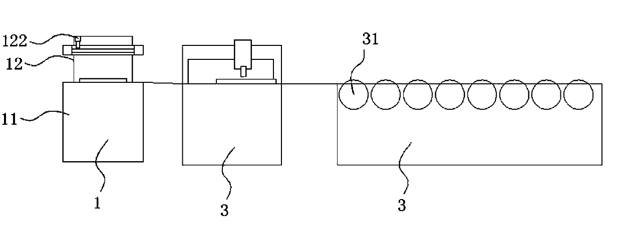
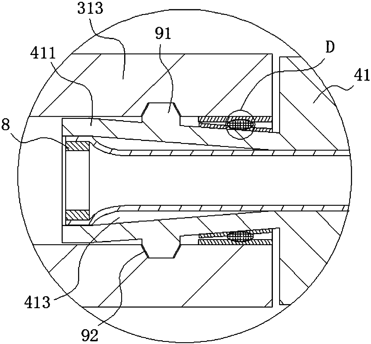
[0026] Such as Figure 1-8 As shown, a system for manufacturing LED lamps includes a pasting mechanism 1, a lamp assembly mechanism 2, and a drying mechanism 3; the drying mechanism 3 includes a chassis, and a plurality of rotatable The drying part 31, the driving part, the air guide channel 32 provided in the drying part and the air supply part for supplying air to the air guide channel; the drying part 31 includes a body part 312 and a body part The connecting parts 313 at both ends, the air guiding channel 32 is set in the body part 312, and one of the connecting parts 313 is provided with an air intake channel 314 communicating with the air guiding part; the drying part ...


PUM


Abstract

The invention discloses a system for manufacturing LED lamps, which includes a pasting mechanism, a lamp assembly mechanism and a drying mechanism; the lamp assembly mechanism includes a bracket, a workbench arranged on the bracket, and can move left and right along the bracket The moving arm and the punch arranged on the moving arm; the drying mechanism includes a plurality of rotatable drying parts, a driving part for driving the drying parts to rotate, and an air guide set in the drying parts. A channel and an air supply component for supplying air to the air guide channel; a number of drying holes communicated with the air guide channel are distributed at intervals on the outer surface of the drying member. In the present invention, the hot air is directly in contact with the LED patch lamp after being sprayed. Compared with the traditional drying method, the drying speed is increased by at least 60%, and the drying efficiency is high; and the hot air is directly contacted with the LED patch after the air is discharged Lamp contact, heat energy loss is small, effectively reduce energy consumption, and realize energy saving and environmental protection.

Description

technical field [0001] The invention belongs to the technical field of LED lamp manufacturing, and in particular relates to a system for manufacturing LED lamps. Background technique [0002] Existing LED lamps generally include a lampshade and an LED patch lamp arranged in the lampshade. When manufacturing LED patch lights, it is necessary to paste the LED lights on the FPC circuit board to form the LED patch lights, and then dry the LED patch lights. The traditional drying method is to convey the LED patch lamp through a rolling steel mesh, and set a heating tube or a hot air blower under the steel mesh, and dry the LED patch lamp during the process of conveying the LED patch lamp by the steel mesh. However, under this structure, the distance between the LED patch lamp and the heating source is relatively long, and the drying efficiency is low. And because of the long distance, a lot of heat energy will be lost directly during the drying process, resulting in high energy...

Claims


Application Information

Patent Timeline
Patent Type & Authority Applications(China)
IPC IPC(8): F21K9/90F21V19/00F21V23/00B05C5/00B05D3/04F21Y115/10
CPCF21K9/90B05C5/002B05D3/0413F21V19/0025F21V23/005F21Y2115/10
Inventor 潘明安
Owner 潘明安
Learn More