
Error analysis method based on vision stitching measurement

An error analysis and error technology, which is applied in the field of error analysis based on visual stitching measurement, and can solve problems such as unexplained quantitative influence relationships.

Active Publication Date: 2018-02-23
DALIAN UNIV OF TECH
View PDF12 Cites 13 Cited by
  • Summary
  • Abstract
  • Description
  • Claims
  • Application Information

AI Technical Summary

Problems solved by technology

[0003] After literature search, Chinese invention patent number: CN 104729534 A, Tan Qimeng, Li Jindong, Hu Chengwei and others invented the "monocular vision error measurement system and error quantification method for cooperative targets" invention patent proposed a monocular vision error measurement The system analyzes the calibration error of the camera's internal parameters, the acquisition error of the three-dimensional space coordinate value of the visual marker point, and the two-dimensional coordinate positioning error in the marked image, and can comprehensively summarize the source of the measurement error, which is of great significance for error traceability. However, the patent The quantitative impact of these errors on the 3D coordinate error of the final point is not explained
Chinese invention patent number: CN 106323337 A, Liu Zongming, Zhang Yu, Cao Shuqing and others invented the invention patent of "A Method for Error Analysis of Stereo Vision Relative Measurement System", which analyzed the image feature extraction accuracy, focal length calibration accuracy, rotation and translation in detail The comprehensive error of the matrix calibration accuracy to the measurement of the three-dimensional target point in space, but only the error of the visual measurement system itself is analyzed, and it cannot be used for the error analysis of the entire system when the visual splicing measurement of large parts is performed

Method used


Image

  • Error analysis method based on vision stitching measurement
  • Error analysis method based on vision stitching measurement
  • Error analysis method based on vision stitching measurement

Examples


Embodiment 1

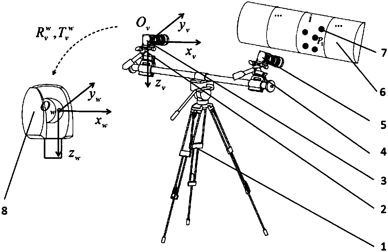
[0054] Example 1, first set up as attached figure 1 The laser tracker-based binocular vision splicing measurement system shown above uses Leica AT960 MR as the measuring head 8 of the laser tracker, and the measurement range is 1‐20m. The left camera 3 and the right camera 5 use VC-12MC-M, with a resolution of 3072*4096 and a maximum frame rate of 60Hz. And use the checkerboard to calibrate the binocular vision system, the obtained camera calibration parameters are as follows: the coordinate value of the principal point of the left camera u 01 = 2140.397824, v 01 =1510.250152; equivalent focal length f x1 =6447.987913, f y1 =6454.015281; the coordinate value of the principal point of the right camera u 02 = 2124.090030, v 02 =1526.184441, equivalent focal length f x2 =6417.044403, f y2 =6420.363610, and the transformation matrix from the left camera to the right camera Arrange 9 public points in the public field of view of the laser tracker and the visual measurement ...


PUM


Abstract

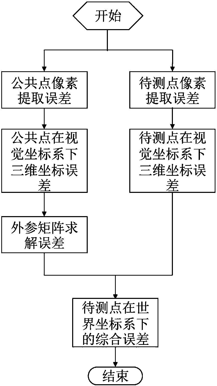
The invention provides an error analysis method based on vision stitching measurement, belongs to the technical field of computer vision measurement, and relates to the error analysis method based onvision stitching measurement. The method is based on a laser tracker and a binocular vision system for stitching measurement. The method comprises the steps that multiple common points are arranged inthe public field of view; a binocular camera is used to collect an image and extract the pixel coordinate of the image; the laser tracker simultaneously collects the coordinate of each common point,and the coordinate value is in a world coordinate system; the influence of the pixel error of point extraction on an external parameter matrix is calculated; the influence of the error of the externalparameter matrix on the coordinate value error of a point in the world coordinate system and the influence of the coordinate of the point in a vision coordinate system on the coordinate value error of the point in the world coordinate system are calculated; and finally the comprehensive error of a point to be measured in the world coordinate system is acquired. The method has the advantages of simple analysis process and clear error transfer chain. The layout of common points is optimized according to error analysis, which improves the overall accuracy of a measurement system.

Description

technical field [0001] The invention belongs to the technical field of computer vision measurement and relates to an error analysis method based on visual splicing measurement Background technique [0002] With the continuous improvement of the manufacturing level of parts in the aerospace field and the automobile industry, people have higher and higher requirements for the precision of parts. The traditional measurement methods for these parts include three-coordinate machine method, laser radar method, indoor GPS method, etc. The machine vision method developed in recent years is also widely used in aerospace due to its advantages of non-contact, fast measurement speed and high precision. and the automotive industry. This method obtains the three-dimensional coordinates of the point in the visual coordinate system by extracting the pixel coordinates of the image captured by the camera, and then uses the conversion matrix from the visual coordinate system to the world coor...

Claims


Application Information

Patent Timeline
IPC IPC(8): G01B11/00G01N21/93
CPCG01B11/005G01N21/93
Inventor 刘巍兰志广张洋张致远邸宏图逯永康马建伟贾振元
Owner DALIAN UNIV OF TECH
Learn More