Structurally integrated piezoelectric inchworm linear motor

A technology of linear motors and electric inchworms, applied in the direction of piezoelectric effect/electrostrictive or magnetostrictive motors, generators/motors, electrical components, etc., can solve the problem of reducing the life of the motor, the clamping force of the clamping mechanism is small, Friction and wear and other problems, to achieve the requirements of reducing processing and assembly accuracy, the overall structure is simple, and the effect of improving service life

Active Publication Date: 2018-02-23
NINGBO UNIV
View PDF5 Cites 13 Cited by
  • Summary
  • Abstract
  • Description
  • Claims
  • Application Information

AI Technical Summary

Problems solved by technology

[0004] However, the current piezoelectric linear motor still has the following deficiencies: 1) The structure is a split type, that is, the clamping mechanism and the driving mechanism are designed and manufactured separately, and then they are assembled into one body. Due to the clamping displacement of the clamping mechanism Or the release displacement is mostly provided by the piezoelectric actuator, and the output displacement of the piezoelectric actuator is often very small, so in order to make the clamping mechanism clamp and release reliably, it is required that the components of the clamping mechanism have very high processing and assembly accuracy; moreover, the small output displacement of the piezoelectric actuator will make the clamping mechanism unable to fully clamp or release, if not fully clamped, the clamping force of the clamping mechanism will be small, and the motor will move The stability is ...

Method used


Image

  • Structurally integrated piezoelectric inchworm linear motor
  • Structurally integrated piezoelectric inchworm linear motor
  • Structurally integrated piezoelectric inchworm linear motor

Examples


Embodiment Construction

[0023] The present invention realizes the continuous linear motion of the output shaft with high resolution and large stroke through the alternating action of the clamping mechanism and the driving mechanism, and its specific implementation is given below.

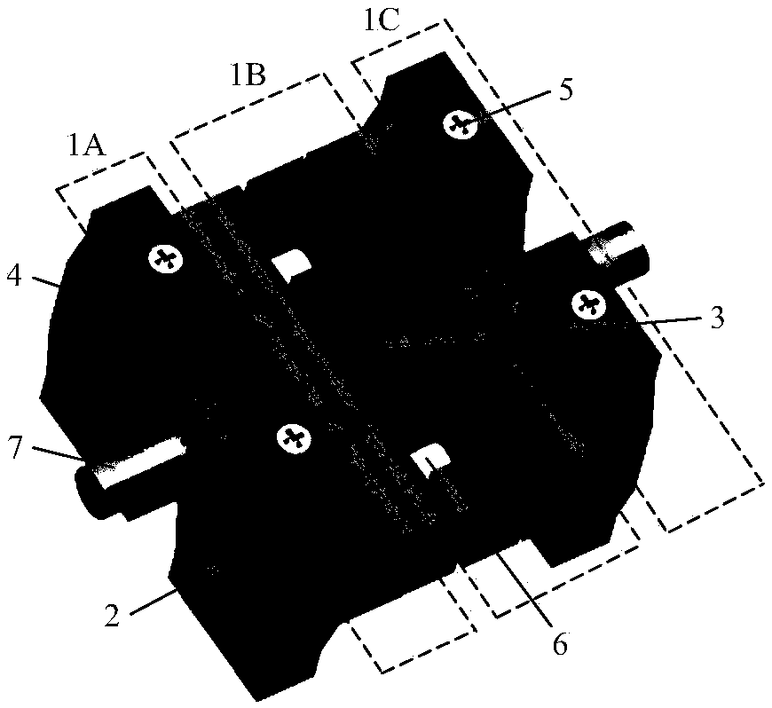
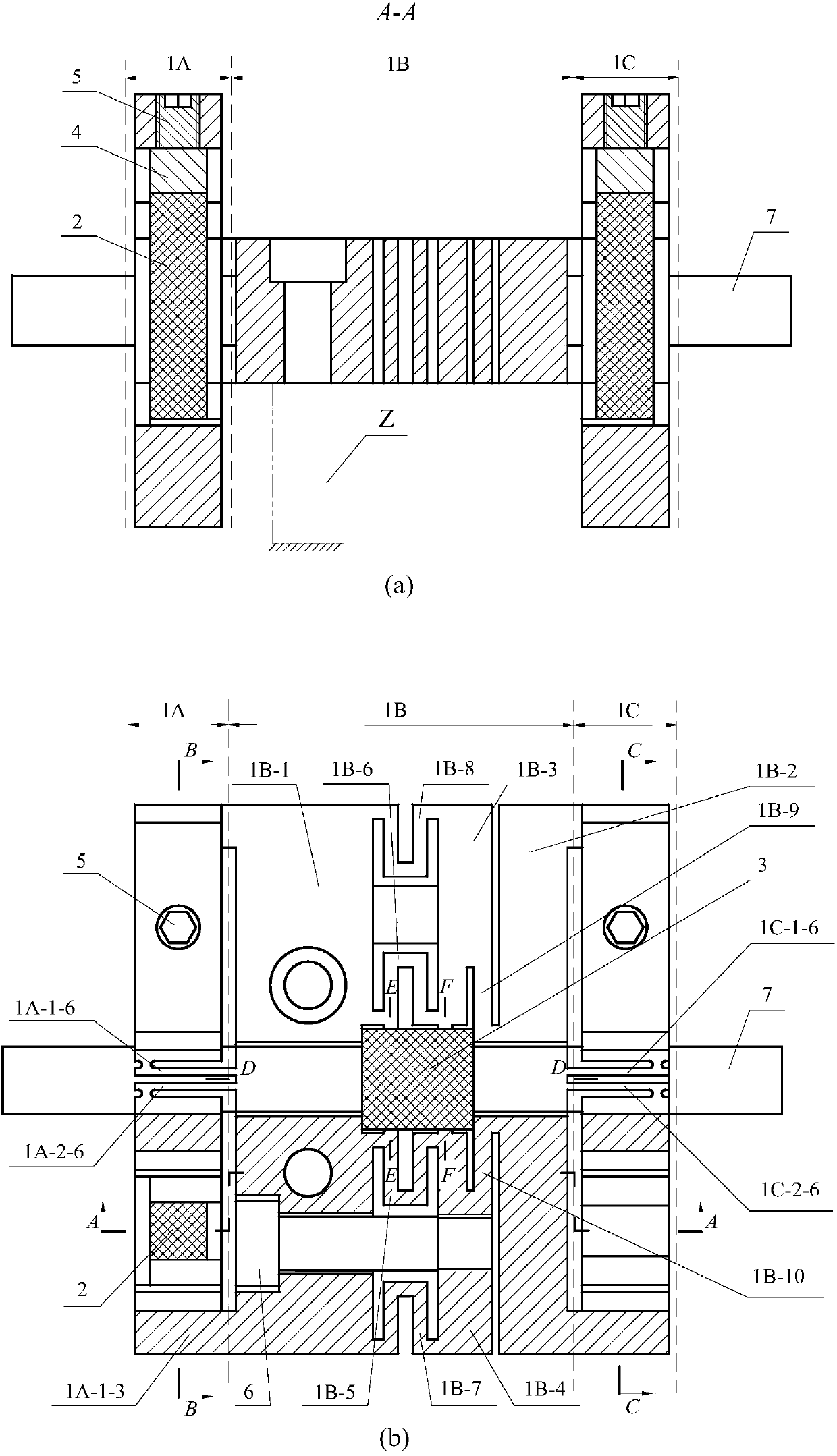
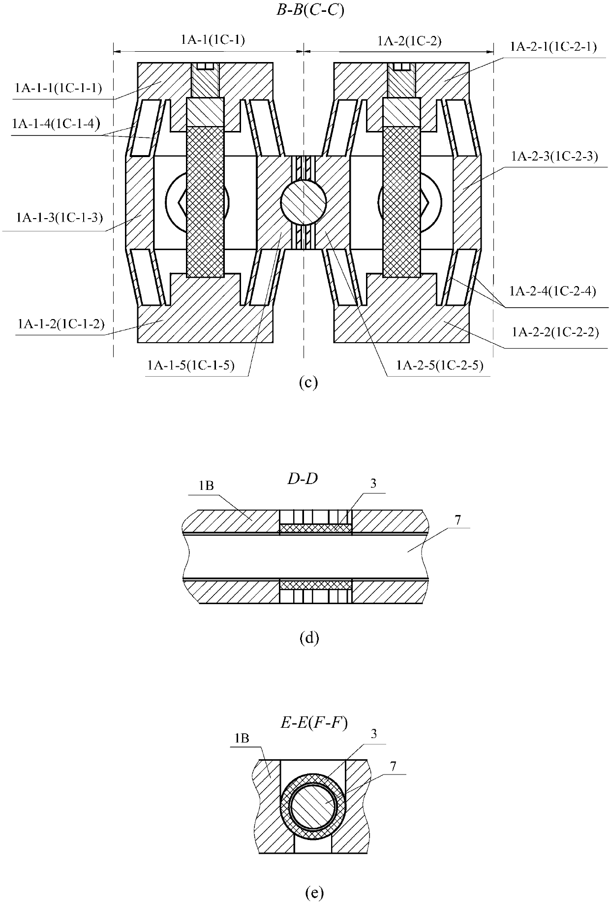
[0024] A structurally integrated piezoelectric inchworm linear motor, such as figure 1 As shown, it includes a body composed of a left clamping mechanism 1A, a right clamping mechanism 1C and a driving mechanism 1B, a piezoelectric actuator 2 for release, a piezoelectric actuator 3 for driving, a pre-tightening pad 4, and a pre-tightening screw 5 , countersunk head pre-tightening screw 6, output shaft 7; the body is an integrated structure, wherein the left clamping mechanism 1A and the right clamping mechanism 1C are symmetrical and have the same structure, and the driving mechanism 1B is located between the left clamping mechanism 1A and the right clamping mechanism Between 1C.

[0025] The left clamping mechanism 1A an...


PUM


Abstract

The invention relates to a structurally integrated piezoelectric inchworm linear motor. The structurally integrated piezoelectric inchworm linear motor comprises a left clamping mechanism, a right clamping mechanism, a driving mechanism, and an output shaft, wherein the driving mechanism is located between the left clamping mechanism and the right clamping mechanism, the left clamping mechanism and the right clamping mechanism are respectively provided with a first clamping body, a second clamping body, and a clamping drive assembly respectively, the driving mechanism comprises a left rigid part, a right rigid part, an intermediate rigid part, a pre-tightening elastic part, a flexible thin plate, and a piezoelectric actuator for driving, a clamping position for clamping the piezoelectric actuator for driving is arranged between the pre-tightening elastic part and the intermediate rigid part, the output shaft passes through the left rigid part, the piezoelectric actuator for driving, and the right rigid part at a time, a pre-tightening screw for pre-tightening the piezoelectric actuator for driving is arranged between the left rigid part and the middle rigid part, and a vacancy forinserting the pre- tightening screw for the piezoelectric actuator for driving is formed in the left clamping mechanism. The structurally integrated piezoelectric inchworm linear motor has the advantages that the clamping mechanism is integrated with the driving mechanism and the piezoelectric actuator can be clamped off when only subjected to pressure.

Description

technical field [0001] The invention belongs to the technical field of micro / nano positioning, relates to a micro-displacement driver in a micro / nano positioning system, in particular to a structurally integrated piezoelectric linear motor. Background technique [0002] In recent years, with the rapid development of information technology and precision testing technology, the demand for large optical devices with microstructured surfaces (such as microlens arrays, micromirror arrays, and gratings) has been increasing. The unit size of the surface microstructure of these optical devices is generally on the order of microns, while the surface size of the entire microstructure reaches the order of millimeters or centimeters. In order to obtain these large optical devices, whether it is for their addition or for the measurement of their processed surface topography, a large-stroke, high-resolution precision positioning system is required, and as the driver of this precision posi...

Claims


Application Information

Patent Timeline
IPC IPC(8): H02N2/02H02N2/04H02N2/06
Inventor 崔玉国王子宾李锦棒马剑强杨依领刘尔春张志豪
Owner NINGBO UNIV
Why Eureka
Try Eureka