Current-limiting detection and protection circuit for NMOS load switch
A load switch and protection circuit technology, applied in circuits, electronic switches, electrical components, etc., can solve problems such as overcurrent, short circuit, and complicated conditions of electrical equipment, and achieve the effect of stable current limiting protection current threshold
- Summary
- Abstract
- Description
- Claims
- Application Information
AI Technical Summary
Problems solved by technology
Method used
Image

Examples
Embodiment Construction
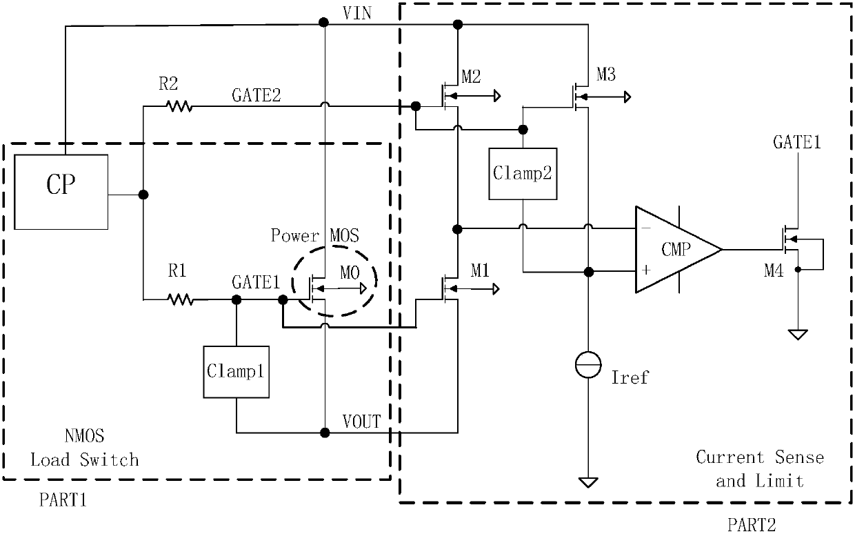
[0011] Such as figure 1 , the PART1 part is an NMOS load switch, including an NMOS power transistor M0, a charge pump CP, a clamp circuit Clamp1 and a clamp current limiting resistor R1. The drain of the NMOS power tube M0 is connected to the power supply VIN, the source of the power tube M0 is connected to the output voltage VOUT and the input terminal of the clamping circuit Clamp1, the gate of the power tube M0 is connected to one end of the clamping current-limiting resistor R1 and the clamping circuit Clamp1 The output terminal of the resistor R1 is connected to the output of the charge pump CP. During normal operation, the output of the charge pump CP provides a high voltage with limited driving capability, and then through the clamping current limiting resistor R1 and the clamping circuit Clamp1, the gate potential of the power transistor M0 is clamped to be about 4.5 higher than the source potential V, so that it is fully turned on, and M0 works in the linear region, ...
PUM
 Abstract
Description
Claims
Application Information
 - R&D
- Intellectual Property
- Life Sciences
- Materials
- Tech Scout
- Unparalleled Data Quality
- Higher Quality Content
- 60% Fewer Hallucinations
Browse by: Latest US Patents, China's latest patents, Technical Efficacy Thesaurus, Application Domain, Technology Topic, Popular Technical Reports.
© 2025 PatSnap. All rights reserved.Legal|Privacy policy|Modern Slavery Act Transparency Statement|Sitemap|About US| Contact US: help@patsnap.com