Filtering based imaging system dynamic range extension method

A technology of dynamic range expansion and imaging system, which is applied in the parts of TV system, image communication, color TV, etc., can solve the problems of image fusion result influence, complex system, expensive price, etc., and realize low cost, The effect of simple system structure and wide application range

Active Publication Date: 2018-02-23
NORTHWEST INST OF NUCLEAR TECH
View PDF4 Cites 4 Cited by
  • Summary
  • Abstract
  • Description
  • Claims
  • Application Information

AI Technical Summary

Problems solved by technology

However, the disadvantage of this method is that the system is too complex and expensive, and the err

Method used


Image

  • Filtering based imaging system dynamic range extension method
  • Filtering based imaging system dynamic range extension method
  • Filtering based imaging system dynamic range extension method

Examples


Embodiment Construction

[0030] A filter-based imaging system dynamic range expansion method proposed by the present invention, the specific implementation steps are as follows:

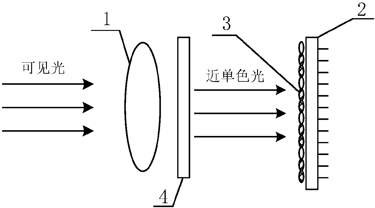
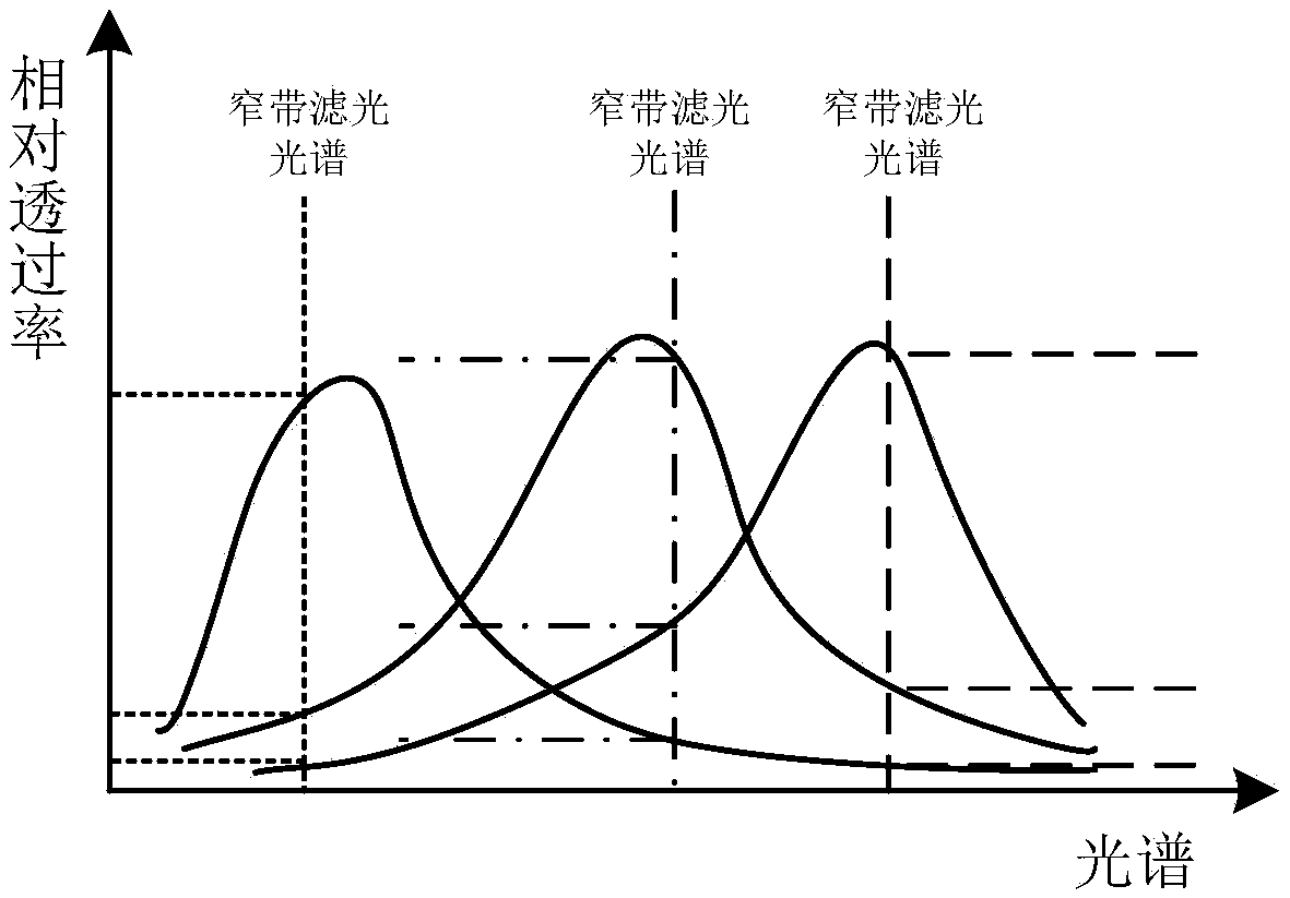
[0031] Step 1: According to the luminescent spectral characteristics of the target scene, the spectral response characteristic curve of the color image sensor or multi-color filter coating or lens, select an appropriate narrow-band filter for spectral selection, so that the approximate monochromatic light image can be filtered in different colors , the intensity attenuation coefficients are quite different; figure 2 , image 3 shown;

[0032] Step 2: Coupling the CCD or CMOS image sensor with the narrow-band filter, the possible coupling structure is as follows figure 1 As shown; in the figure, 1 is an imaging lens, 2 is an image sensor, 3 is a color microlens, and 4 is a narrow-band filter;

[0033] Step 3: For the coupled imaging system, image acquisition is performed under different light intensities, and sub-images c...


PUM


Abstract

The invention provides a filtering based imaging system dynamic range extension method, is particularly suitable for obtaining a big dynamic image in a superfast high-intensity light-emitting processand is simple and clear in system structure and low in implementation cost. The image sensor in the imaging system adopted by the method is a color image sensor or a grey image sensor covered with a multi-color coating film or a multi-color lens. The method comprises the following steps of selectively filtering a wide-spectrum visible image of an imaging scene into an approximate monochromatic light image by utilizing a spectrum selection function of a narrowband filter; obtaining multiple sub-images with different attenuation coefficients through multi-color filtering, wherein the sub-imageswith the relatively small attenuation coefficients can obtain scene images with relatively low brightness, and the sub-images with relatively big attenuation coefficients can obtain scene images withrelatively high brightness; and obtaining a high dynamic range image with high resolution through sub-image interpolation calculation.

Description

technical field [0001] The invention relates to a method for extending the dynamic range of an imaging system, in particular to a method for extending the dynamic range that can be widely used in visible light imaging systems. Background technique [0002] Modern visible light imaging systems usually use image sensors as photosensitive devices. Currently, there are two main types of image sensors: CCD image sensors and CMOS image sensors. Due to the limitation of the physical structure of the semiconductor image sensor, the potential well depth of the photosensitive area of ​​the CCD or CMOS image sensor is limited, and usually only tens of thousands of induced charges can be accumulated, especially the CMOS image sensor, which has a small photosensitive surface and a high degree of integration. In this case, the charge potential well in the photosensitive area is smaller. When the visible light intensity range of the target scene is large and the dynamic range of the imagi...

Claims


Application Information

Patent Timeline
IPC IPC(8): H04N5/225H04N5/232H04N5/235
CPCH04N23/55H04N23/54H04N23/951H04N23/741
Inventor 严明杨少华魏福利李刚刘璐郭明安李斌康夏惊涛罗剑辉
Owner NORTHWEST INST OF NUCLEAR TECH
Why Eureka
Try Eureka